Page 5 of 12
Zip CH103, CH104 - Installation & operating instructions - 82127UK - June 2015 v1.04
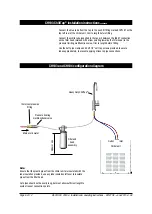
Refer to the configuration diagram page 6.
Note
It is important to install an isolating valve (not supplied) in the incoming mains
cold water supply line before the connection to Zip chiller products.
Installing the chiller and filter head
Site the under counter chiller unit into the cupboard as close to the dispensing tap
position as is possible, to minimise the length of tubing exposed between the chiller
unit and the dispensing tap. Secure the filter head to the wall, cupboard side or
back (with the 2off 3/4” self tap screws provided) in a convenient location between
the incoming mains water supply and the chiller unit, again minimise tube lengths
where possible. Allow 260mm minimum clearance between the underside of the
filter head and any obstructions .
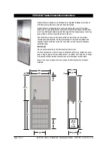
Allow an envelope of at least 50mm around the chiller unit to permit free airflow.
Both the top and the front of the chiller must remain accessible for servicing
purposes.
Electrical connection
Electrical connection must be made by a Zip service engineer or a qualified
electrician. (See Safety information page 2).
Connect to water supply
Install the isolation valve (not supplied) in the mains cold water supply line, in the
under-counter cupboard space. Using the 15mm compression fitting supplied,
connect the pressure limiting multifunction valve assembly to the incoming water
supply line.
Note
Before assembling the compression fitting to the valve, apply sufficient PTFE
tape to the thread to ensure a water tight connection.
Do not turn the water on until the complete system has been connected.
Installing the tap
Install the Heavy duty ChillTap
®
in a position where there is a
Ø
45mm wide flat
area within the draining area of the sink, ensuring that the selected position allows
the water from the spout to safely drain away.
Use a 22mm sheet metal punch to create a neat hole without burrs.
Remove the plastic nut and lower rubber washer from the base of the tap, leaving
the rubber-sealing ring in place, then fit the tap in place, oriented so that the lever
is operated towards the user.
Slide the lower rubber washer and plastic nut over the tap connection tubes, (under
the sink), and tighten the nut to secure the tap firmly into place.
Connecting the system together
Note
Ensure that the plastic pipes from the chiller unit are insulated with the tube
insulation provided, use any tube insulation left over to insulate pipes from the filter
head.
The pressure limiting multifunction valve supplied must be fitted.
Ensure that all connections to push fit fittings are pushed in past the O-ring to full
depth, at least 15-16mm (see diagrams opposite).
Connect the white tube from the tap to the outlet of the filter housing. (marked with
arrow pointing away from filter head), trim to length before fitting.
Connect the red tube from the tap to the push fit fitting marked INLET on the top
right rear of the chiller unit, trim to length before fitting.
CH103 ChillTap
®
installation instructions


