background image

- CS Commercial HydroTap - Installation Instructions - 09.16 v3.01 

Page 17 of 20

1. 

Note:

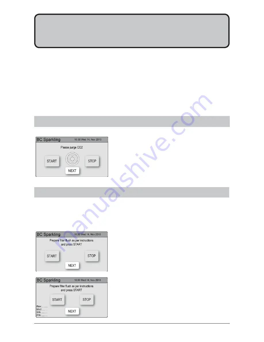
 You will need to Press the [Start] [Stop] buttons 

to start and stop the filter flush.

2. 

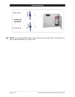
Turn the flush line stop cock ON  (See diagram).

3. 

Press [Start] and allow at least 10 litres of water to flush 
through the filter.

4. 

The product details will be displayed in the screen.

5. 

Once the filter flush is finished, Turn the stop cock OFF 
then press [Stop] to end filter flush mode. 

6. 

Press [Next] for the Boiling Calibration screen.

Have a 10L bucket or similar container (not supplied) at the ready to hold a quantity of water that will be 
ejected while the Filter Flush Mode is in operation. Open the filter access door on the front of the HydroTap 
and the filter cartridge will be exposed. Located to the rear RHS of the cartridge is a flush line, approx 600mm 
long and the flush line stop cock. Place the valve end of the flush line into the 10L bucket or container.    

5.2

 - 

Filter Flush 

Section 5

Commissioning


5.1

 - 

CO2 Purge

1. 

Press the [START] button to commence the purging 
process. 

2. 

Purge for 10 seconds and ensure all water has stopped 
flowing through the tap. (You will hear the CO

2

 gas 

escaping from the tap).

3. 

Press the [Stop] button.

4. 

Press [Next] for the filter flush screen

The HydroTap is now ready to be commissioned. 

• 

Turn ON the water and gas and check for any leaks.

• 

Turn the power ON at the GPO 

• 

Familiarise yourself with the operation of the Tap, in preparation for use (See User Guide)

• 

Follow the instructions below (and review Section C of the User Guide). 

• 

Initially you will be prompted to select a language

• 

After commissioning, the system may be customised by selecting further options in                     

Section G - Settings, within the User Guide.

Summary of Contents for HydroTap G4 CS175

Page 1: ...nstallation Instructions 09 16 v3 01 Page 1 of 20 Zip HydroTap G4 Installation Instructions Filtered Chilled and Sparkling drinking water for commercial kitchens and tea rooms Affix Model Number Label Here 801910 CS Commercial ...

Page 2: ...changeable taps to suit the customer s needs See options below For ease of installation it is recommended to fit the tap before installing the undersink unit The installation procedure for each of the taps is detailed in a separate tap installation instruction book No 803341 supplied with the tap For all operational features of the HydroTap please refer to the CS User manual No 801981 ...

Page 3: ...on 2 1 Ventilation All Models 10 2 2 Ventilation diagram CS Models 10 11 2 3 Alternative Ventilation 11 STEP 3 Fit the CO2 Gas cylinder Section 3 CO2 Cylinder and Regulator 3 1 Connect secure and test the CO2 gas cylinder 12 3 2 Connect the regulator 12 3 3 Connect the gas hose 12 CO2 Regulator 13 Leak test 13 STEP 4 Install the underbench unit Section 4 Underbench unit installation 4 1 Hose and T...

Page 4: ... appliance when full of water Before Commissioning 1 Check the unit has been installed correctly 2 Flush the supply line before connecting to the undersink unit 3 Check all plumbing fittings have been tightened 4 Ensure the outlet and vent pipes are positioned to drain correctly 5 Ensure there is adequate ventilation 6 Check all tubes from the underbench unit to the tap have a constant rise and th...

Page 5: ... have been given supervision or instruction concerning use of the appliance by a person responsible for their safety Children should be supervised to ensure that they do not play with the appliance For products sold in Europe this appliance can be used by children aged from 8 years and above and persons with reduced physical sensory or mental capabilities or lack of experience and knowledge if the...

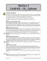
Page 6: ... Due to the process of continuous improvement Zip Heaters reserves the right to change details mentioned in this manual without notice 2 64 Kg CO2 Cylinder Warnings Pressurised container Protect from sunlight Contains gas under pressure may explode if heated Do not expose to temperatures exceeding 50 C Do not pierce or burn even after use Do not expose to naked flame or any incandescent material K...

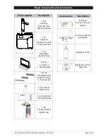
Page 7: ...nd water filters 1 off Mains water connection hose Duct kit 1 x Air Duct 1 x Mounting plate Vent Kit 1 x Kickboard louvre 1 x Door vent louvre 1 x Front vent grill 1 x Tee piece for Celsius model 1 x User guide and 1 x Quick start guide 1 off CO2 gas cylinder regulator assy Guide Accessories Description Font Kit for Celsius Arc Cube Models Font Kit for Classic Elite Models Replacement Filter Disab...

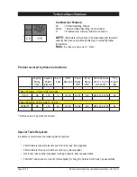
Page 8: ...ull of water Capacity Boiling cups Capacity Chilled glasses Boost 10A GPO s Required Power Rating kW Boost Rating kW Unit Dimensions W x D x H mm with air duct Dry Weight Kg Chilled Sparkling Classic Elite Arc Cube CS175 NA 175 no 1x10A 0 450 NA 336 x 476 x 335 26 Chilled Sparkling Hot Ambient Celsius CSHA175 NA 175 no 1x10A 0 450 NA 336 x 476 x 335 26 Special Tools Required In addition to normal ...

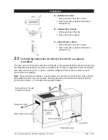
Page 9: ...ble water supply connection with isolating valve inside the cupboard within reach of the braided hoses and positioned so that the connection point and the stop cock will not be obstructed when the undersink units are installed For the Celsius tap an external Hot and Cold water supply will be required A cold water supply with a minimum working pressure of 250kPa and a maximum working pressure of 70...

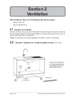
Page 10: ...ll vent duct and louvre panels for under floor and or door vent systems Note Inlet and outlet vents should be separated by a Min 100mm to avoid hot air recirculation When installing air flow ducts the following tools will be required Jigsaw and 12mm drill Keyhole or Wall Board saw Section 2 Ventilation Typical Cut out arrangement for Chilled Sparkling models with kickboard venting via a left hand ...

Page 11: ...then it is important to fit a standard HydroTap vent kit which ensures heat dissipation through natural convection via installed vents For high use applications where the cupboard space temperature is near 35 C or higher an auxiliary ventilation kit must be fitted Contact your local service centre for availability Note The vent kit has to be installed in a way that allows air to be drawn in from t...

Page 12: ...sy fit over the spigot soak it in hot water before re applying Do not force the seal to fit Turn the regulator OFF by rotating the regulator knob all the way out in an anti clockwise direction NOTE Two plastic seals are supplied with a new regulator Only one is required the other is supplied as a spare part 3 3 Connect the gas hose Connect the braided gas hose to the top of the underbench unit via...

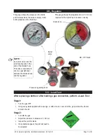
Page 13: ...spect the joint for leaks 4 If any bubbles appear the joint will need to be resealed CO2 Regulator 5 5 Leak Test This gauge shows the pressure in the bottle and indicates when the bottle is empty Initial bottle pressure will be 35 40 bar This gauge shows the adjustable limit 2 7 3 0 bar required for the HydroTap to function correctly Pressure regulating knob ON OFF knob Green zone Relief valve NOT...

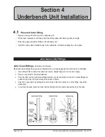
Page 14: ...gs Insertion and removal Be careful when cutting the poly tube so that there are no rough edges and that the tube is not distorted 1 Use a sharp knife to ensure the tube has a clean straight edge Do not cut at an angle 2 Remove any swarf or unwanted material 3 Push the tube into the John Guest fitting making sure all connections to the John Guest fittings are pushed in past the O ring to full dept...

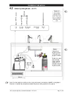
Page 15: ...e and therefore CANNOT be lengthened Take time to consider hose lengths when determining the mounting positions for the options Note Mains hose length is 750mm Plug and Cord length is 1800mm Position the under sink unit close to the outlet tap within reach of the hose and cord lengths supplied Note Note All All silicon tubes silicon tubes must be cut to must be cut to size They must size They must...

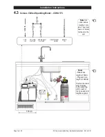
Page 16: ...h is 750mm Plug and Cord length is 1800mm Position the under sink unit close to the outlet tap within reach of the hose and cord lengths supplied Note Note All All silicon tubes silicon tubes must be cut to must be cut to size They must size They must have a constant have a constant fall back to the fall back to the unit unit 4 3 Celsius Chilled Sparkling Model CSHA 175 Installation Instructions ...

Page 17: ...exposed Located to the rear RHS of the cartridge is a flush line approx 600mm long and the flush line stop cock Place the valve end of the flush line into the 10L bucket or container 5 2 Filter Flush Section 5 Commissioning 5 1 CO2 Purge 1 Press the START button to commence the purging process 2 Purge for 10 seconds and ensure all water has stopped flowing through the tap You will hear the CO2 gas...

Page 18: ... Instructions 09 16 v3 01 OPEN Position CLOSED Position ON OFF Stop cock operation Commissioning NOTE For any subsequent filter changes or any operational procedures please refer to the HydroTap user guide located inside the filter housing access door ...

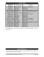
Page 19: ... run Compressor too Hot Check ventilation Water supply failed No water Check water supply is turned ON Cold sensor Open Internal fault Call Zip Service Cold sensor Closed Internal fault Call Zip Service Flood sensor Open Internal fault Call Zip Service Condenser sensor Closed Internal fault Check Ventilation Call Zip Service Condenser sensor Open Internal fault Check ventilation Call Zip service C...

Page 20: ...979 GB0422305 GB2065848 US4354049 US5103859 US5099825 and SA2006 08043 Other patents are in force and patent applications are pending Head Office Zip Heaters Aust Pty Ltd ABN 46 000 578 727 67 Allingham Street Condell Park NSW 2200 Postal Locked Bag 80 Bankstown 1885 Australia Website www zipwater com Facsimile 02 9796 3858 Telephone 02 9796 3100 Free Call 1 800 638 633 As Zip policy is one of con...

Reviews: