background image

127899 Rev. A

33

Z I PP I E   Z M- 3 1 0

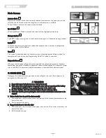
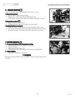
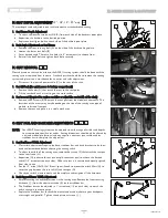
M. SEAT DEPTH ADJUSTMENT 

10" - 18", 12" - 20" only  

The seat depth can be adjusted in one inch increments on standard rehab seating.

1. Seat Frame Depth Adjustment

a. To adjust, remove the two bolts (A & B) from each side of the backrest pivot plate.
b. Reposition the backrest to the desired position.
c. Replace and retighten bolts on each side of the backrest pivot plate.

2. Back Angle Adjustment on Seat Frame

a. Remove the front securing bolt (A) on the side of the backrest hinge plate.
b. Loosen the lower rear bolt (B)
c. Set at desired angle. There are five holes (in 4º increments) to choose from.
d. Reinstall the front bolt and tighten both bolts securely.
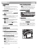
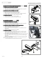
N. SEAT REMOVAL 

Most adjustments that can be made to the ASAP II seating system, should be done with the
seating system removed from the base.  Standard practice should be to remove the seating
system and place it on a workbench for an easier and safer adjustment.

a. Disconnect the joystick power cable (C) in the rear of the chair.

1. Seat tilt back (for quick access to battery compartment)

a. Remove the knobs (D) that attach the seat to the seat posts.
b. Tilt the seat back until it is resting on the work surface.

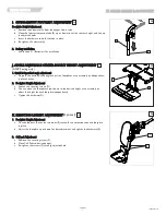
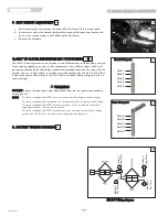
2. Seat removal (required to replace modules or adjust the seat width of the chair)

a. Remove the 4 screws (E) to detach the seat pan from the modules underneath.  The

locations of the screws may vary depending on the size of the seating area, type of
module, and size of seat pan.

b. Remove the seat and place it in a stable work area.

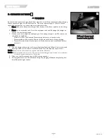
O. SEAT PAN AND BACK SIZE ADJUSTMENTS 

NOTE:  Your ASAP II seating system can be adjusted to a wide range of widths and depths

to accommodate specific user needs.  Seating dimensions should only be altered by
a trained medical professional and may require a new seat pan, cushion and/or 
stabilizer bar to complete the adjustment.

1. Seat Pan/Frame Width Adjustment

a. Most width adjustments require the back, stabilizer bar,  and back brackets to be loos-

ened and/or removed before adjusting the seating width.

b. To adjust the width of the seating area, remove the screws (F) that attach the seat pan

to the seat frame (H).

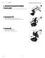
c. Reposition (G) (either solid seat pan, or split-cover seat pan) to achieve the desired

width (1/2” increments on each side).  Make sure that it is centered and equally spaced
from side to side.

d. For the 13” wide, (10x10-13x18 seat), you will need to mount the width fillers (H)  to

cover the gap between the seat rail (H) and seat pan (G).

e. Check your width measurements and then replace and retighten all the hardware.

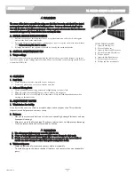
2. Back Support Frame Width Adjustment

a. After measuring the width adjustment in the seating area, Remove the front securing

hardware ( J ) from the adjustment tube (K) on the stabilizer bar.

b. The Stabilizer bar can be adjusted in 1” increments(1/2’ on each side) to match the

width change in the seating area.

c. Replace the Stabilizer bar, recheck the measurement and make sure your backposts

are straight and parrallel.  Tighten the adjustment screws ( J ) 

60

62

61

63

64

65

XI. DEALER SERVICE & ADJUSTMENT

61

63

C

60

A

B

64

65

62

D

F

J

G

H

K

E

I

Summary of Contents for ZM-310

Page 1: ...al must be given to the rider of this wheelchair User Before using this wheelchair read this entire manual and save for future reference SECTION ENGLISH ZM 310 M a n u a l d e I n s t r u c c i o n e s Zippie ZM 310 BC SC M o d e d e m p l o i Zippie ZM 310 BC SC ...

Page 2: ...oduction 16 B Cleaning 16 C Storage tips 16 D Tire pressure 16 E Motor brushes 16 F Disposing of Batteries 16 G Ordering parts 16 H Maintenance chart 16 I Folding Backrest 17 J Swing in out Footrests 17 K Elevating Legrest 17 L Angle adjustable centermount footrest 17 M Dual post fixed height standard and Dual post height adjustable armrests 18 N Single post height adjustable armrests 18 O Manual ...

Page 3: ... actuator control SC only Option RNET LED or Color Batteries 2 deep cycle batteries required to operate chair Standard Group 22 Battery Charger Off board 8 AMP Shroud Colors Red Black Blue Silver Copper Green Apple Yellow Pearl Pink Candy Purple Matte Black Midnight Blue Pearl white Pink Camo Grunge skulls American Flag Seats Upholstery and Style Standard BC SC A S A P II Seat Frame Sizes 10 16 wi...

Page 4: ...heelchair you will see the icons listed below to identify warnings and potential haz ards WARNING These warnings must be followed failure to do so may cause personal injury or may dam age the wheelchair ESD Electrostatic Discharge can damage printed circuit boards V EMI ELECTROMAGNETIC INTERFERENCE WARNING Heed all warnings to reduce the risk of unintended brake release or chair movement 1 Beware ...

Page 5: ...lly tested with the ZM 310 and RNET control system WARNING Individuals with physical limitations requiring the use of a specialty control input device known not to be immune to 20V m or not known should exercise extra care around known sources of EMI WARNING There is no way to know the effect on EMI if you add accessories or modify this chair Any change to your chair may increase the risk of EMI P...

Page 6: ...chair WARNING Heed all warnings in this section If you fail to do so a fall tip over or loss of control may occur and cause severe injury to you or others A NOTICE TO USER AND ATTENDANTS WARNING User 1 Before using this chair you should be trained in its safe use by your health care professional 2 Every wheelchair is different Take the time to learn the feel of this chair before you begin riding 3...

Page 7: ...rain 3 Do not operate the chair on sand loose gravel or soil Doing so may damage wheels bearings axles motors or loosen fas teners J STREET USE WARNING 1 This product is not intended for street use 2 Avoid streets whenever possible 3 Obey and follow all legal pedestrian pathways and laws that apply to pedestrians 4 Be alert to the danger of motor vehicles in parking lots or if you must cross a roa...

Page 8: ...orward M TRANSFERS WARNING It is dangerous to transfer on your own It requires good balance and agility Be aware that there is a point during every transfer when the wheelchair seat is not below you To prevent a fall 1 Always turn off power before you transfer to or from your chair If you fail to do so you may touch the joystick and cause your chair to move when you do not expect it 2 Make sure mo...

Page 9: ...heelchair lifts are used in vans buses and buildings to help you move from one level to another 1 Always turn off all power to your chair when you are on a lift If you fail to do so you may touch the joystick by acci dent and cause your chair to drive off the platform Be aware that a roll stop at the end of the platform may not prevent this 2 Make sure there is not a lip or drop off at the top or ...

Page 10: ...m to a height of more than 22 measuring from the front of the seat pan to the floor with all actuators in their home position WARNING Note If you use parts or make changes not authorized by Sunrise it may create a safety hazard and will void the Warranty A ARMRESTS WARNING 1 Armrests will not bear the weight of this chair 2 Never lift this chair by its armrests They may come loose or break B BATTE...

Page 11: ...ion your seat is going to move before operating 2 Reduced Speed Driving Creep This power chair is designed to automatically reduce the maximum driving speed to a creep mode when certain power seating limits are reached 3 Pinch points Pinch points may occur when operating the powered seating options on this chair Ensure all hands and body parts are clear of all power seating components that may res...

Page 12: ... Installation a Install the pelvic belt D onto the pelvic belt securement point anchored to the seating frame of the Zippie ZM 310 Using a 10mm Hex key torque the screw to 144in lbs securing the pelvic belt to the mounting anchor E b Repeat step 1 for the opposite side VEHICLE ANCHORED BELTS WARNING This wheelchair has an overall rating of A with regard to accommodating the use and fit of vehicle ...

Page 13: ...ion 18 ISO 10542 compliant rear securement straps be used to anchor the power chair during motor vehicle transport For power chairs that exceed the weight threshold mentioned above It is further recommended that the vehicle used for trans port have a gross vehicle weight greater than 8800lbs 4000Kg if the option exists WARNING The buckle of the belt restraint system should not be located near any ...

Page 14: ... have a complete safety check and service of your chair performed by a supplier B CLEANING 1 Paint Finish Clean the paint finish with mild soapy water monthly Protect the paint with a coat of non abrasive auto wax every three months 2 Motors Clean around motor area weekly with a slightly damp not wet cloth Wipe off or blow away any fluff dust or dirt on or around the motors NOTE You do not need to...

Page 15: ...ocks into place on locking plate 2 Removal a To remove footrest release latch B by pulling lever upward or pushing lever downward b Rotate footrest inward or outward and lift it out of the front frame tube K ELEVATING LEGREST Optional 1 Installation To install or remove Elevating Legrest ELR see instructions for Swing away Footrest instal lation 2 Adjustment a To raise legrest lift to desired posi...

Page 16: ...rn securing lever to locked position d Move armrest up or down to allow armrest to snap into place N SINGLE POST HEIGHT ADJUSTABLE ARMRESTS Optional 1 Installation a Slide the outer armpost into the receiver mounted to the wheel chair frame b The armrest will automatically lock into place 2 Height Adjustment a Rotate release lever to stop b Slide armrest pad up or down to desired height c Return l...

Page 17: ...chair rotate this knob clockwise and turn the knob counter clockwise to return the back to a more upright position P JOYSTICK Controls Two types of joysticks are available LED and Color Display The joystick assembly has 3 components The Joystick The Power Module and the communications cable Q OMNI INPUT DISPLAY The Omni is a universal specialty controls interface that accepts signals from many dif...

Page 18: ...nector into its mate until you can no longer see the yellow plastic The connectors are secured using a friction system To disconnect the communication cables Holding the connector housing firmly pull the connectors apart NOTE Do not hold or pull on the cable Always grip the connector when connecting and discon necting When the control system is first switched on after a connection or system compon...

Page 19: ...controller cord Make sure to avoid any areas where the cord may be pinched Adjustment and or switch sides a To adjust the joystick forward or back loosen the clamp A move the joystick and then hand tighten the clamp handle b To move the joystick to the opposite side of the chair remove the hardware B and move the clamp and joystick receiver to the other armrest c Tighten all hardware to avoid any ...

Page 20: ...range can be programmed from 1 to 50 in steps of 1 Default setting is 1 WARNING Before turning on or adjusting these parameters carefully read and understand the implications for use of these features Joystick Stationary Time and Joystick Stationary Range When the Joystick Stationary Time is reached within the Joystick Stationary Range the drive motors on the chair will shut off As an example this...

Page 21: ... If you do you may shorten the life off the wheelchair drive components Actuator Indicator This LED set displays which actuator channel is currently being controlled when the control system is in Actuator Mode Actuator selection and operation is achieved using the joystick Motions to the LEFT or RIGHT select different actuator channels Motions FORWARD and BACKWARD move the actuator s selected Batt...

Page 22: ...is well Flashing Slowly The control system is functioning correctly but you should charge the battery as soon as possible Stepping Up The wheelchair batteries are being charged You will not be able to drive the wheelchair until the charger is disconnected and you have switched the control system off and on again If the battery gauge shows red yellow and green the batteries are charged bars 1 10 If...

Page 23: ...ented from moving the wheelchair a diagnostics screen will be displayed This indicates a system trip i e the RNET has detected a problem somewhere in the wheelchair s electrical system G BRAKE LEVER Disengage the brake lever when you need to manually push the chair For example in an emergency or if batteries fail WARNING 1 Do not disengage brake lever unless chair power is off 2 With either one or...

Page 24: ...urrent AC supply is higher or lower than 110 volts 2 Caution To Avoid Damage to the Charger Never place the charger on top of a battery during charging Gases from the battery can damage the charger and may lead to an explosion or fire Never place a battery on top of the charger Never expose charger to rain or snow Never unplug charger by pulling on the electrical cord This will damage the cord Nev...

Page 25: ...rea is well vented Never charge battery in a closed in area Never smoke or allow a spark flame or high heat near battery during charging Never allow metal tools or chair parts to make direct contact across both battery terminals ALWAYS 4 Use the charger that comes with your wheelchair Read and follow all instructions and warnings Make sure the room is well ventilated Turn off all power to your cha...

Page 26: ...pecified When not specified torque settings should be set at a minimum of 60 in lbs C CLEANING 1 Paint Finish a Clean the painted surfaces with mild soap or detergent b Protect the paint with a coat of non abrasive auto wax 2 Axles and Moving Parts a Clean around axles and moving parts with a slightly damp not wet cloth b Wipe off or blow away any fluff dust or dirt on axles or moving parts c DO N...

Page 27: ...hroud a Position the shroud and hand thread a few screws to hold the shroud in place b You can then insert the other screws while moving the shroud to line up the holes c Be sure not to tighten screws too much because it could fracture the plastic F BATTERY REMOVAL 1 To remove the batteries before transporting or servicing a Carefully flip back the seat see Section O Seat removal b Remove the shro...

Page 28: ...iver forwards or backwards for a universal fit c Tighten the hardware when adjustment is complete 2 Adjusting Armrest Angle or levelling the armrest after height adustment a Loosen the pivot bolt E on the armrest angle bracket b Remove the Socket head screw and hardware F c Adjust the angle of the armrest and joystick and re insert the hardware thru the adjusted hole d Tighten all hardware when ad...

Page 29: ...epress the button C and angle adjust the footplates as an assembly or independant ly of each other 2 Footplate Height Adjustment a Loosen the securing screws D b You can move the footplates up or down to the desired height as an assembly or adjust the height for each footplate independantly c Tighten the hardware D K ELEVATING LEGREST ADJUSTMENT Optional 1 Footplate Height Adjustment a To raise fo...

Page 30: ...trest assembly out of the receiver 2 Footplate Height Adjustment a Remove the six securing screws B b Move the footplate up or down to the desired height c Re install screws B through adjusted holes and tighten the hardware 3 Calf pad Adjustment a Remove the two securing screws C b Move Calf Pads to desired height c Re install screws C through adjusted holes 59 58 57 57 58 59 57 58 59 A B C ...

Page 31: ...odule and size of seat pan b Remove the seat and place it in a stable work area O SEAT PAN AND BACK SIZE ADJUSTMENTS NOTE Your ASAP II seating system can be adjusted to a wide range of widths and depths to accommodate specific user needs Seating dimensions should only be altered by a trained medical professional and may require a new seat pan cushion and or stabilizer bar to complete the adjustmen...

Page 32: ... floor matrix in the Zm 310 service manual before changing any of the factory settings WARNING DO NOT increase the front post height independent from the rear posts when providing seating pre tilt NOTE For chairs configured with SPOT tilt do not increase the Pre tilt greater than 3 degrees For chairs configured with seat elevator do not increase the Pre tilt greater than 3 degrees For chairs confi...

Reviews: