13
11
09
10
!
12
35
35
CHAPTER 8
REPAIRS / TROUBLESHOOTING
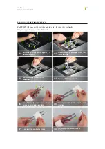
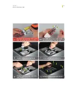
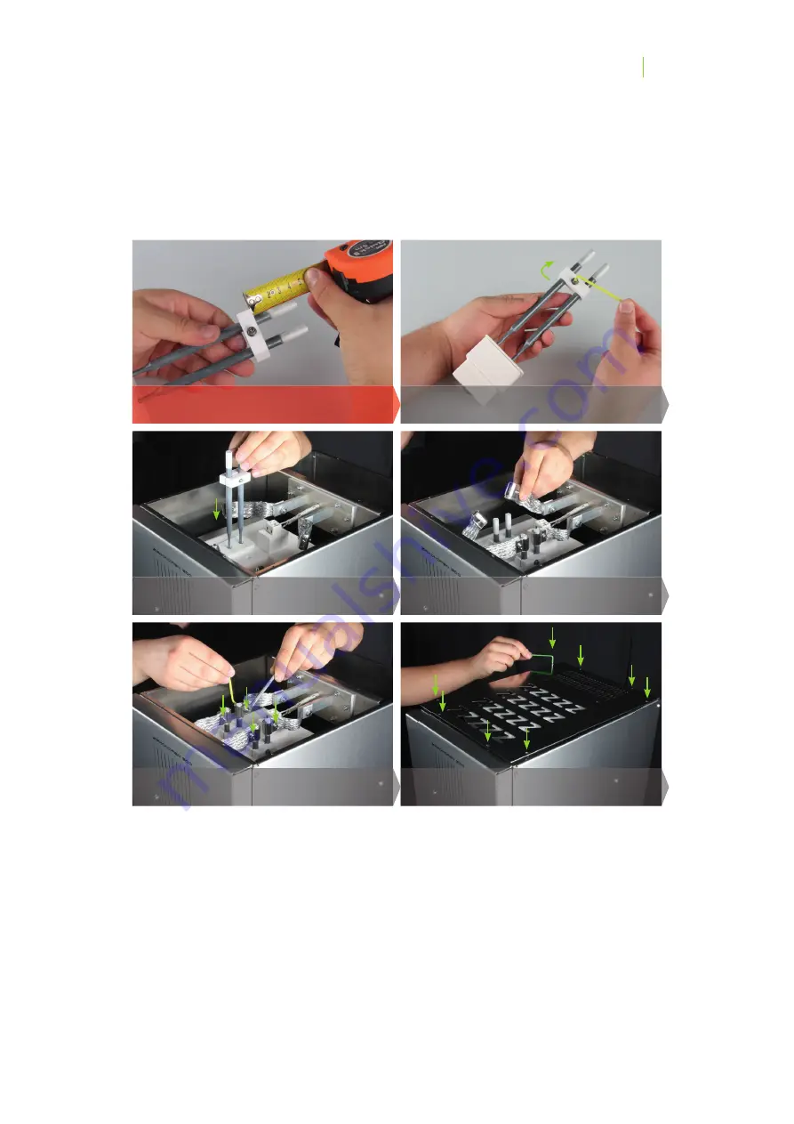
Position the cover panel and fi x the 8 screws.
Fix the contact strips on the contact pins.
Use the Allen key to properly fi x the ceramic
terminal block (Caution: risk of breakage).
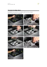
Carefully insert the new heating elements.
The ceramic terminal block has to be mounted
at 3.6 – 3.7 cm from the heating element’s end.
Properly screw the 4 clamping screws to the
contact strips.
Summary of Contents for ZIRCONFEN 600
Page 1: ...zirkonofen 6oo 6oo V2 operator s and maintenance manual...
Page 3: ...03 03...
Page 6: ...06 06...
Page 7: ...07 07...
Page 10: ...10 10...
Page 18: ...18 18 CHAPTER SAFETY RESIDUAL RISKS...
Page 19: ...19 19 CHAPTER 2 COMPONENTS COMPONENTS...
Page 22: ...22 22 CHAPTER 3 TECHNICAL DATA...
Page 26: ...26 26 CHAPTER 4 INSTALLATION FIRST START UP...
Page 28: ...28 28 CHAPTER 5 OPERATION...
Page 30: ...30 30 CHAPTER 6 SINTERING PROGRAMMES...
Page 38: ...38 38 NOTES...
Page 39: ...39 39...

