background image


3.2. Detector Positioning In Atrium.


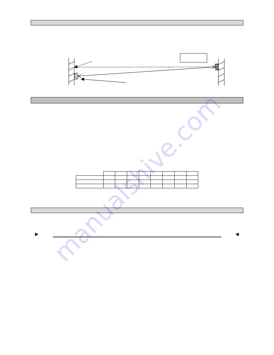
If the detector is to be placed in an atrium, or near glass/polished surfaces, the prism(s) should be offset from 
the central line of sight (approximately 300mm), and angled back to the beam detector. This can be either on 
the vertical or horizontal axis. This will reduce the amount of spurious returned signal from the glass/polished 
surfaces. The reflected signal from the prism(s) will be returned to the detector in the normal way. 


4. Installation. 

 
Pre-installation at Ground Level. 
 
Confirm that all parts have been supplied as listed in the parts list. See page 10. 
 
Select the required alarm threshold using configuration switches 3 and 4 (See page 8, fig. 4. for switch 
configuration settings). The factory default setting is 35% this should be adequate for most environments, if the 
Detector is to be installed into an exceptionally dirty environment change the threshold to 50%. 
 
Select the required address using address switches 1 to 7 (See page 9, Table 1. for address switch settings) 
where 1 is ‘ON’ and 0 is ‘OFF’.  The factory default setting is address 1. 
 
Shown below is an example of address 85 (1+4+16+64 = 85).  


SW1 SW2 SW3 SW4 SW5 SW6 SW7 SW8 

Switch 

Value 1 2 4 8 16 

32 

64 X 

Switch 

Position ON OFF ON OFF ON OFF ON  X 

Logic 

1 0 1 0 1 0 1 X 

 
The Detector Head Assembly is now ready for installation. If configuration switches 3 and 4 require resetting 
after installation, a power down reset is required (entering into Alignment Mode can also be used as a reset). 
 

4.1. Detector Head Assembly Installation.


Remove the outer cover before installation; this is only to prevent the cover becoming dislodged during 
handling. 


Do not mount on plasterboard or cladded walls as these surfaces do, and will move. 

 
Determine the position of the Head Assembly, which


must be mounted on a 

solid structure

 between 0.5 and 

0.6 metres below the ceiling, and no closer than 0.5 metres to an adjacent wall or structure. Ensure that there is 

clear line of sight

 to the proposed position of the prism(s), which is to be mounted on a solid structure 

between 5 and 100 metres directly opposite the Detector (range dependent on model). 
 
Using the template provided mark and install all 4 fixing points to the structure. The rear mounting plate of the 
Detector Head Assembly is provided with 4 keyhole slotted apertures to allow for easy installation onto the 4 
fixing points. Install the detector on the four mounting points. 
 
Replace the outer cover. 
 
Terminate the field wiring. See section 8. 


Offset Prism(s) position and beam path 

Normal Prism(s) position and 

central line of sight 

Detector 
head 

Plan View 

www.acornfiresecurity.com

www.acornfiresecurity.com

Summary of Contents for ZP7BMR-100

Page 1: ...Range 50 100 Metres Unique simple alignment Loop powered Selectable alarm thresholds Low current consumption Automatic contamination compensation ZITON ZP7BMR 50 100 Loop Powered Analogue Addressable...

Page 2: ...ism Targeting page 5 6 Alignment page 5 to 7 7 System Testing page 7 8 Connection and configuration Settings page 8 9 Detector Back View page 9 10 Address settings page 10 11 Clearances page 11 12 Tec...

Page 3: ...ondition being rectified The Detector monitors long term degradation of signal strength caused by component ageing or build up of dirt on optical surfaces This operates by comparing the received infra...

Page 4: ...creased from 7 5 metres either side of the beam to 7 5 7 5 x 20 100 metres 9 metres Therefore with a roof pitch of 20 degrees the lateral coverage can be increased from 7 5 metres either side of the b...

Page 5: ...ON OFF ON OFF ON X Logic 1 0 1 0 1 0 1 X The Detector Head Assembly is now ready for installation If configuration switches 3 and 4 require resetting after installation a power down reset is required...

Page 6: ...horizontal and vertical thumbwheels until the Amber LED is flashing Both the Red and Amber LED will be OFF when no signal is being received The Red LED will start to flash when a weak signal is receiv...

Page 7: ...be receiving a fringe reflection from another object FLICKERING RED AMBER This state can occur sometimes It means that the infrared power is stepping through the optimum setting for the current orient...

Page 8: ...n filter to correspond with the Detector alarm threshold see fig 3 Place the filter over the receiver optics Top of Detector Head opposite end to the status indication LED s at the correct obscuration...

Page 9: ...itch with the following features The address settings is set up via the 8 way DIP switch on the lower part of the beam See Fig 4 8 3 Typical Loop Wiring Fire Panel Connections Loop Output Input to Nex...

Page 10: ...9 Detector Interface Assembly Configuration Settings DIP SWITCH SETTINGS X X X X X X X X X X X X X X X X X X X 2 X 1 3 4 Fig 4 www acornfiresecurity com www acornfiresecurity com...

Page 11: ...0001011X 19 1100100X 62 0111110X 105 1001011X 20 0010100X 63 1111110X 106 0101011X 21 1010100X 64 0000001X 107 1101011X 22 0110100X 65 1000001X 108 0011011X 23 1110100X 66 0100001X 109 1011011X 24 000...

Page 12: ...ameter clearance down the entire beam path If there are highly reflective objects within 1 metre diameter of the beam path for the first 20 metres of the beam path for the ZP7BMR 100R then tests shoul...

Page 13: ...rt 5 use 25 and 35 default thresholds The threshold of 50 is recommended for hostile and extreme environments When in normal run mode the fire panel controls the Red LED flashing Amber LED flashing on...

Reviews: