4
7
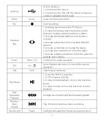
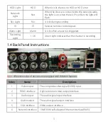
USB interface
1. Connecting the mouse;
2. Connecting the USB with the device to back up videos
or upgrade the firmware.
8
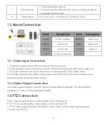
Power input
DC 12V/2A, DC 12V/3.3A, DC 12V/4A, AC220V.
1.5 Alarm Connection
1.5.1 Alarm Input Connection
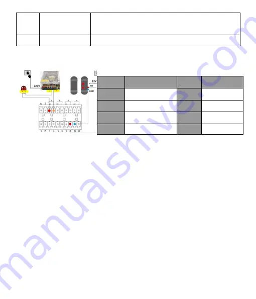
1. Grounding alarm inputs. (Normal open or Normal close)
2. Please parallel connect the ground of the DVR and the ground of the alarm detector.
3. The alarm detector’s NO port should be connected to the DVR’s alarm input.
4. The alarm detector should be connected to the DVR’s GND end once the detector is
powered by the external power supply.
1.5.2 Alarm Output Connection
The alarm output signal is a switch signal, normal open by default. The alarm output
equipment needs an external power supply.
1.6 PTZ Connection
PTZ’s “+” terminal should be connected to DVR’s interface “A”;
PTZ’s “-” terminal should be connected to DVR’s interface “B”.
1. PTZ’s video output interface should be connected to DVR’s video input interface.
2. Power up the PTZ.
Name
Descriptions
Name
Descriptions
A/B
RS485 interface
NO1.C
Alarm out
NO2.C
Alarm out
NO3.C
Alarm out
NO4.C
Alarm out
1
-
8
Alarm in
G
Ground interface


