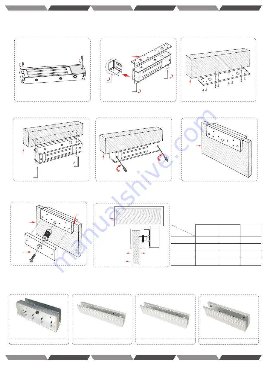
(Downside Frameless Glass Door: AL-180PU , AL-280PU, AL-350PU,AL-500PU)
AL-180PU
AL-280PU
140
195
29
29
40
40
AL-350PU
195
29
40
AL-280PU
AL-350PU
Diagram of Magnet ic Lock Auxiliary Bracket Installation Procedures
Step 1: Use cross screwdriver to dismount the
anti-dismantle screw on the lock.
Step 3: Use screws to fix the connecting plate
to the doorframe and fix relevant positions.
Step 4: Use Allen key to install the lock onto the
doorframe connecting plate in corresponding
position.
Step 6: Install U- bracket to the glass door and
align it with lock position on the doorframe. Then
fix it with screws.
Position
Model
Length
Width
Height
Doorframe
Door frame
Install the tamper screw
Door frame
Door frame
Glass door
Glass door
Glass door
Small metal
plate for height
adjustment
Screw
Outside
Inside
Step 7: Use screws to fix the sub-plate and
the U- bracket. Their positions shall be
consistent. Make sure the rubber ring is
installed during installation.
AL-180PU
Step 8: Installation effect
Electric Strike Series
Magnetic Lock Series
El ect ric Bolt Lock ser ies
Brackets and Accessories
Me cha ni cal Lo ck Se riess
El ec tron ic Lo ck Se ries
Electric Strike Series
Magnetic Lock Series
El ect ric Bolt Lock ser ies
Brackets and Accessories
Me cha ni cal Lo ck Se riess
El ec tron ic Lo ck Se ries
Step 2: Use Allen key to separate the connecting
plate from the bottom of the lock.
Schematic
diagram
Connecting plate
Step 5: Use cross screwdriver to install wire box
cover and the anti-dismantle screws.
AL-500PU
AL-500PU
198
66
42


