background image


Chapter 2 The Installation of the Device 

2.1 Installation notes 

2.1.1 It is recommended that the full height turnstile should be installed on a cement platform with 

50mm to 100mm in height. 

2.1.2 It is recommended that the full height turnstile should not be used in corrosive environments. 

2.1.3 Make sure the earth wire of the system is connected reliably reliably to prevent any personal 

injuries or other accidents. 

2.1.4 After completion of the installation, check the connection condition of earth wire, connector 

assembly for connecting line and all moving parts with the device. Make sure the connection is 

firm in order to prevent failure caused by long time operation. If any screw or part is not tightened, 

please tighten. 


2.2 Installation position of the full height turnstile 

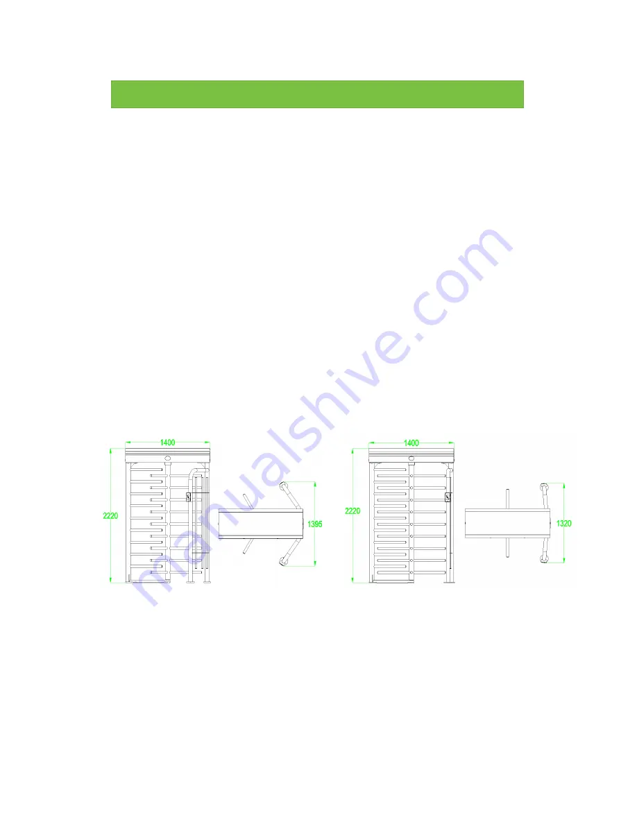
The installation position are subject to the size of the full height turnstile, as shown in Figure 2-2A. 

Figure2-2A 


2.3 Installation and fixation of cables


The following diagram shows the interface of the concealed cable. The input voltage for this full 

height turnstile is AC100-120V/200-240V. The PVC conduits are buried 100mm below the ground, 

with the height of the exposed part not not less than  100mm. To prevent water leakage to the 

Summary of Contents for FHT2311

Page 1: ...USER MANUAL Full Height Turnstile Applicable Models FHT 2300 2400...

Page 2: ...tiles 3 1 6 Product related parameters 3 Chapter 2 The Installation of the Device 4 2 1 Installation notes 4 2 2 Installation position of the full height turnstile 4 2 3 Installation and fixation of c...

Page 3: ...wo KR101E reader InBio260 with two FR1200 ID reader FHT2300 FHT2311 FHT2322 FHT2400 FHT2411 FHT2422 1 2 Structures and dimensions FHT2000 series has stainless steel casing which provides corrosion res...

Page 4: ...re mainframe box 1 4 Electronic control system The electronic control system of the full height turnstile is composed of reader control panel access controller direction indicator horn and transformer...

Page 5: ...fter the access controller send the signals to the control panel the control panel will send out a pass 1 5 3 After receiving the signal from the access controller the control panel sends signals to t...

Page 6: ...onnector assembly for connecting line and all moving parts with the device Make sure the connection is firm in order to prevent failure caused by long time operation If any screw or part is not tighte...

Page 7: ...5 conduit the conduit mouth needs to be bent back FHT2300 FHT2400 series installation holes are as shown in Figure 2 3A and Figure 2 3B Figure2 3A Figure2 3B 25 PVC pipe 25 PVC pipe...

Page 8: ...screw and fix it After that the mainframe box is fixed on the frame Finally install the whole rotating part in the middle of the frame as shown in Figure 2 3C Figure2 3C After fixing the device open...

Page 9: ...7 Figure2 3D...

Page 10: ...Move down menu or reduce value OK Use to enter the menu item settings or to confirm the current value ESC Use to return to the previous menu or cancel the current operation 3 3 Menu operation and des...

Page 11: ...are allowed to pass Y N stand for being allowed on the right and forbidden on the left N Y stand for being forbidden on the right and allowed on the left N N stand for being forbidden on both sides Y...

Page 12: ...t 8 Device number Press UP and DOWN buttons to adjust values Press OK button to save When plural devices are placed together different device number can be used to distinguish the default number is 1...

Page 13: ...on mechanism Check and tighten others connection parts 4 3 Power maintenance Cut off power supply before maintenance Check whether the plug is loose if loose it needed to tightly it Please do not repl...

Reviews: