background image

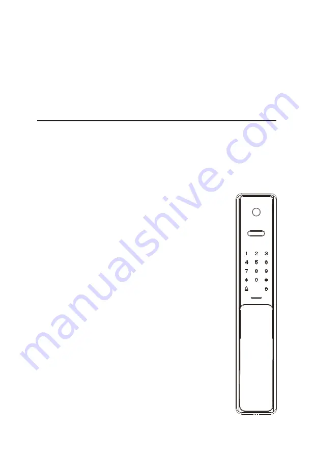
Model: HBL400

Installation Guide

Version: 1.0

Summary of Contents for HBL400

Page 1: ...Model HBL400 Installation Guide Version 1 0 ...

Page 2: ... can occur due to incorrect installation We regularly revise the contents of this Installation Guide and update our products to enhance quality and performance without prior notice 1 2 3 Do not install the batteries until the lock is installed 4 What s in the Box 1 Installation Diagram 2 Installation Procedure 2 1 Door Properties 2 2 Drill Holes on the Door 3 3 Install Mortise and Cylinder 4 4 Uni...

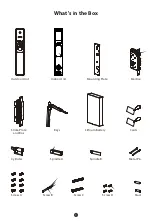
Page 3: ...1 What s in the Box Outdoor Unit Indoor Unit Mounting Plate Mortise Cylinder Spindle B Spindle A Metal Pin Stud Screw A Screw C Screw B Screw D Strike Plate and Box Keys Lithium Battery Cards ...

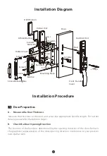
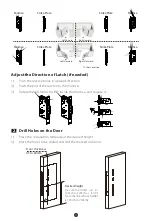
Page 4: ...ection B The position of the handle is determined by the opening direction of the door Below is the graphical representation of the door opening direction in reference to your position outside the room Metal Pin Outdoor Unit Stud Keys Screw A Strike Plate and Box Mortise Screw D Mounting Plate Hidden Cover Metal Pin Screw B OLED Screen Door Indoor Unit Lithium Battery Cylinder Front Handle Cover S...

Page 5: ... User Location Left Inward Right Inward Left Outward Right Outward Rotate the latch bolt to 180 inside the mortise and release it 3 Place the installation template at the desired height Mark the holes to be drilled and drill the marked locations 1 2 2 Drill Holes on the Door Desired height Door thickness 45 to 60mm Backset 60mm recommended up to 100cm to 120cm as it is fit for someone whose height...

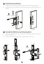
Page 6: ...of indoor unit Uninstall the screw D and take the Mounting Plate off the indoor unit 1 2 3 Install Mortise and Cylinder Put the Mortise into the hole that was drilled and secure the Mortise with Screw A Insert the Cylinder into the Mortise the front sides and back sides and secure it with Screw B 1 2 Front Screw A Screw B Front Screw D ...

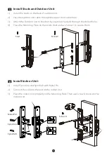
Page 7: ... door by inserting the studs through the drilled holes Place the Mounting Plate on the inside door and use Screw C to secure them 3 4 6 Install Indoor Unit Install Spindle A and Spindle B with Metal Pin Connect the cable to the port on the Indoor Unit 1 2 Place the Indoor Unit properly on the Mounting Plate Then use Screw D to secure the Indoor Unit 3 Screw D Spindle A Spindle B Metal Pin ...

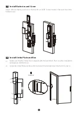
Page 8: ...installation template to drill the holes 1 Align the Strike Plate and Box with the holes drilled and protect them with Screw A 2 8 Install Strike Plate and Box Insert Lithium Battery and cover them with an OLED Screen model then push back the hidden cover Screw A Indoor 31mm 22mm 27mm 2 8mm 171mm 261mm 45mm ...

Page 9: ...e cover from the bottom of outdoor unit then rotate the cover 90 1 Press the bottom of key hole cover and rotate it 180 2 Test the lock by using the mechanical key Insert the Key into key hole and rotate 90 then the latches will be retracted 3 ...

Page 10: ...Version 1 0 User Manual Model HBL400 ...

Page 11: ...lock after installation and set the Administrator immediately to avoid others opening the door illegally 2 3 Please keep your Administrator s information confidential 4 Please keep the mechanical keys in a separate place to avoid any criticality 5 To use the lock more efficiently please refer the User Manual before using the lock If you have any queries please feel free to contact the Company s Clien...

Page 12: ...e First Administrator 3 5 Programming the Features through Menu Mode 3 Quick Start 5 Unlocking Door with Face 5 Unlocking Door with Fingerprint 5 Unlocking Door with Password 5 Unlocking Door with Card 5 How to use OLED Screen Model 6 Overview 6 Programming the Features through Menu Mode 6 How to connect USmart Go APP 8 Setting 8 Functions 11 ...

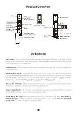
Page 13: ...89123456 etc Backup Enrollment After the first registration users can change the registered password and card or continue to register the remaining fingerprints Always Open Mode This function is to keep the door always unlocked which is suitable for meeting rooms and places with no access restriction Low Battery Warning When the battery power is low the lock will prompt Low battery please change aft...

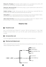
Page 14: ... it is out of power How to Use Press and hold the Reset button for 5 seconds The lock will beep for 5 times Keep holding the Reset button until you hear the audio prompt please press key to confirm 1 Reset the Lock 2 Activate the Lock Touch the keypad with the back of your hand or fingers to activate the lock Before using formally need to make some mechanical adjustment to eliminate something wrong ...

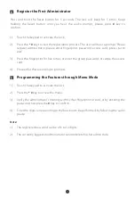
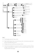
Page 15: ...p for 5 times Keep holding the Reset button until you hear the audio prompt please press key to confirm 4 Register the First Administrator Touch the keypad to activate the lock 1 Press the key to start the registration process The user will hear a prompt Please register administrator please enter fingerprint password access card press star to exit 2 Press the fingerprint for five times or enter the gr...

Page 16: ...ructured Light Facial Recognition Model for few seconds To delete the Face only do that by entering the number 1 2 3 4 The 3D Structured Light facial recognition function is not really suitable for strong sunlight environments if unlock at this environments please verify with fingerprint password card key ...

Page 17: ...It will wake up and verify your face automatically If it does not wake up automatically then you need to wake up the lock manually Unlocking Door with Password Touch the keypad to activate the lock Enter the registered password and press the key to confirm Note Users may enter a random password to prevent any person from observing the password The maximum length of random password is upto 32 digits...

Page 18: ...ming the Features through Menu Mode Press Down button to enter menu choose Camera Files or Set mode freely through buttons Press Power On button to activate the model camera mode 1 2 Up Power Off OK Power On Down Back Camera Files 16 00 2021 5 7 Set ...

Page 19: ...ide choose Auto when press doorbell key the model will power on automatically 4 Camera Angle Choose All Angle customer can watch 360 scenario but the shape of objects will distort choose Undeformed will not 5 6 Auto Power Off Schedule the power off timing Language Change the language of this model 7 8 Date Time Set the date and time of this model Format Will delete all of data in TF card please cons...

Page 20: ...etting Step 2 Create an Account Launch the USmart Go App and register an account you can register by your phone number or email address Step 3 Create Family Every device associated with a Family needs to follow the steps to create a family Menu My Families button or click Add Families button directly only fit for no families before situation ...

Page 21: ... Add Device button directly only fit for no device before situation or click the ADD button at the upper right corner choose Add Wi Fi Device item you ll see Connect hotspot page Press the key and verify administrator on the lock to enter administrator menu Click 4 6 to enter the network configuration mode 1 2 Go to the WLAN setting on your phone and connect to the Wi Fi with the name as CloudHome X...

Page 22: ... to another Wi Fi when connecting Wi Fi Step 6 Finish After getting connected please go back to Connect hotspot page and wait for the page until it goes to Select Wi Fi page then connect a valid Wi Fi and wait until finish Note Please close Cellular Data if you are staying on Connect hotspot page for a long time after connecting Wi Fi ...

Page 23: ...gger a remote unlock request then you ll see a popup window on our app where you need to enter your security password to unlock Owner self unlock Click the Unlock icon you ll see a popup window on our app then enter your security password to verify and press the Doorbell key once the lock will unlock ...

Page 24: ...on lock page then click on the top right corner to change to Add User page and fill out the authorizations information then click Next to generate password Note Password is 7digits on the Generate password page the last one is 1 by default ...

Page 25: ...Edit User page then name the user at the blank after finishing click OK button 3 Name the Lock Click the More button on the lock page a popup window will be appeared choose Settings to go to the Setting page then click the Device Name to rename this lock and after finishing click OK button ...

Page 26: ...14 5 Check Records All of the event records are displayed on the lock page customer can click them to check ...

Page 27: ...l not occur in a particular installation If this equipment does cause harmful interference to radio or television reception which can be determined by turning the equipment off and on the user is encouraged to try to correct the interference by one or more of the following measures IMPORTANT Any changes or modifications not expressly approved by the party responsible for compliance could void the us...

Reviews: