Barrier Gate-ProBG3000 Series
User Manual
P a g e
| 14
Copyright©2020 ZKTECO. CO., LTD. All rights reserved.
5.2
Input Interface
•
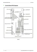
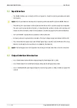
The RS485 interface can connect with the computer to check the barrier gate state and alarm
information.
NOTE: Only the professional developers can operate, ask the sales staff to provide RS485 Protocol.
•
The parking lot open/close control signal and remote control open/close signal are separate.
The arm opening has memory function, it remembers the number of pulse arm opening and
closes once the counted number of cars passes by. (must be equipped with a vehicle detector)
•
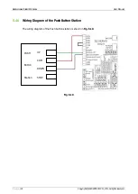
"UP" and "DOWN" signal ports are available on the mainboard.
•
All input ports are in optoelectronic isolation. The input voltage range lies between DC5 to 24V.
•
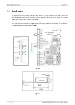
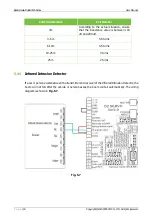
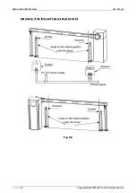
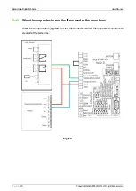
The vehicle detector signal input and infrared signal input uses the output COM, NC of the loop
detector. (normally the No.4 and No.11 are related to the detector)
NOTE: The barrier gate does not respond to the closing command when the coil is not connected.
5.3
Output Interface Introduction
•
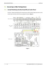
Line 1 Barrier Gate Vertical Position Signal, Relay Dry Node Signal (NC, C, NO).
•
Line 1 Barrier Gate Horizontal Position Signal, Relay Dry Node Signal (NC, C, NO).
•
Line 1 10A R&G Traffic Light Signal, Relay Dry Junction Signal (NC, C, NO), contacts can pass 10A
current.


