background image


 SBTL8000 series User Manual


 3 

1.5


Operation principle of the speed gates 


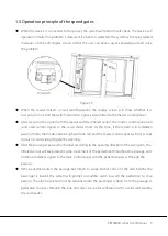
When the device is connected to the power, the system will perform self-check. The device will 

operate normally if no problem is detected. If a failure is detected, the system will display related 

messages on the LCD display screen so that the user can have a quick knowledge of and solve 

the problem. 


Figure 1-3 


When the reader detects a valid card/fingerprint,  the display screen will show whether it is 

successful or not. And the switch instruction signal is transmitted to the master control panel. 


After receiving the signal from the reader and the infrared sensor, the master control panel will 

send  valid control signals to the servo motor driver. At this time, if the system is in forbidden 

passing mode, the mode indicator light will turn red, and the master control panel will not accept 

signals of card swiping/fingerprint scanning. 


After the passenger passes the channel according to the opening direction of the swing arm, the 

infrared sensor will keep detecting the movement of the pedestrian throughout the passage and 

continue to deliver signals to the main control panel until the pedestrian passes through the 

passage. 


If the pedestrian enters the passage but forgets to swipe his/her card, or if the card held by the 

passenger  is invalid, the system will prompt an audible alarm to  warn the pedestrian  to stop 

passing. The alarm signal will not be cancelled until the passenger retreats from the passage. A 

pedestrian can pass through the lane only after successful verification with a valid card read by 

the card reader. 

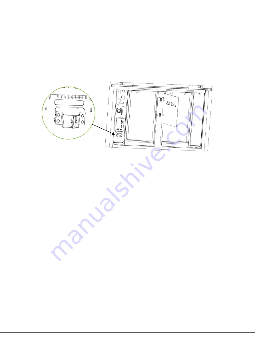
Air switch 

Summary of Contents for SBTL8000 Series

Page 1: ...User Manual Speed gates SBTL8000 series Applicable Model s SBTL8000 SBTL8011 SBTL8022 SBTL8033 SBTL8200 SBTL8211 SBTL8222 SBTL8233 Version 1 0 Date June 2019...

Page 2: ...of the speed gates 3 1 6 System composition of the product 4 1 7 Specifications 4 2 Installation of the Product 5 2 1 Installation notes 5 2 2 Installation position of the speed gates 5 2 3 Cables ins...

Page 3: ...011 SBTL8022 SBTL8033 SBTL8200 SBTL8211 SBTL8222 SBTL8233 Figure 1 1 1 2 Chassis design and dimensions The SUS304 stainless steel body looks simple and clean and is anti corrosion The SBTL8000 series...

Page 4: ...l panel the infrared sensor the mode indicator and the loudspeaker Master control panel The master control panel is the core part of the control system that receives signals from the photoelectric swi...

Page 5: ...vo motor driver At this time if the system is in forbidden passing mode the mode indicator light will turn red and the master control panel will not accept signals of card swiping fingerprint scanning...

Page 6: ...g the normal working mode normally open mode normally closed mode and testing mode After supplying power to the device the LCD screen on the control board will display a default state which is the cur...

Page 7: ...b the surface with hard objects Do not rinse the device with water otherwise there may be short circuit or damaging the equipment 5 After installation check if the connection is done correctly at the...

Page 8: ...re connected with an 8 core cable signal and a 2 core cable power When installing the speed gates turnstile the user only needs to connect it to the corresponding ports Note that the PVC conduits are...

Page 9: ...base on the ground according to the size as shown in Figure 2 3a Use a hammer drill to drill M12 screw holes then install the screws Place the swing turnstile according to the size and respective inst...

Page 10: ...er on test If the test is passed tighten the screws It is recommended to mark a warning line on the ground as shown in Figure 2 3b after installing the device to remind the pedestrian to stand behind...

Page 11: ...value ESC to return to the previous menu or cancel the current operation 3 Operation and instruction of menu Press the ENT button and enter the password input interface The default password is UP UP...

Page 12: ...Close the door and voice alarm Voice alarm only default Turn off reverse detection 5 Trailing alarm detection Mode Turn off trailing detection Voice alarm only default Close the door and voice alarm...

Page 13: ...aximum value 15 Audio prompt for gate opening swift Enable or not No default Yes 16 Infrared anti pinch Mode Turn off the anti pinch feature Enabling anti pinch default 17 Infrared anti pinch area Are...

Page 14: ...12 SBTL8000 series User Manual 3 3 Functions introduction of wiring and terminal Figure 3 2...

Page 15: ...te unlocked Check the mode setting of the master and slave devices and the 8 core 2 core connection lines See the wiring diagram for the specific connection circuit 3 The barrier doesn t close when th...

Page 16: ...te the transmission mechanism Check and tighten others connection parts 5 3 Power Cut off the power supply before maintenance Check the plug connection if anything is loose fix it Do not randomly chan...

Page 17: ...Copyright 2019 ZKTECO CO LTD All rights reserved ZK Building Wuhe Road Gangtou Bantian Buji Town Longgang District Shenzhen China 518129 Tel 86 755 89602345 Fax 86 755 89602394 www zkteco com...

Reviews: