User’s Manual for ZKMD3 Series IR
Vandal-proof Dome IP Camera
Document Version: 1.7
Date: 2012.10
Introduction
This document mainly introduces the functional features, installation process and
access methods of ZKMD3 series IPC. .
Page 1: ...l for ZKMD3 Series IR Vandal proof Dome IP Camera Document Version 1 7 Date 2012 10 Introduction This document mainly introduces the functional features installation process and access methods of ZKMD...
Page 2: ...epend on the actual product Since the product is subject to updating our company is not responsible for any difference from this guide and not liable for any dispute over different technical parameter...
Page 3: ...ct Appearance 5 1 5 Connecting Terminals 7 1 6 Basic Procedure 11 2 Installation and Network Configuration 12 2 1 Hardware Installation 12 2 2 Operating Environment 17 2 3 Network Connection 17 3 Acce...
Page 4: ...h definition or common pixel standard definition cameras which can be wall mounted or ceiling mounted easily installed and operated and used in indoor or outdoor places The products are applicable for...
Page 5: ...b indicator lamps for easy judgment of web status 4 9mm focus adjustable lens adjusted according to different environment Analog video output interface for HD to facilitate site commissioning Self rec...
Page 6: ...mps 10 15m effective projection distance 60 degrees projection angle Video Coding Primary Processor Hi3512 Operating System Embedded Linux Video Compression Algorithm H 264 main profile level 3 Audio...
Page 7: ...as Control Interface 1 RS485 Memory Support TF card for video storage and image capture 32G maximum optimal Network Interface 10Base T 100Base TX Ethernet interface WiFi 802 11b g wireless optional Su...
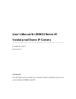
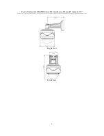
Page 8: ...ing mounted mode fixing base camera transparent cover Diagram of wall mounted mode fixing base camera transparent cover wall mounted bracket Dimensional drawing of ceiling mounted mode in mm Right Vie...
Page 9: ...User s Manual for ZKMD3 Series IR Vandal proof Dome IP Camera V1 7 6 Right View Front view...
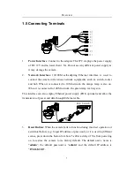
Page 10: ...ange lamp is also on When it is connected to 100M network the green lamp is always on This interface can also employ Ethernet power supply POE optional and allow the transmission of power and data thr...
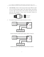
Page 11: ...hile triggering a remote alarm The specific interfaces are presented in the following figure IN 1 2 3 4 5 NC COM NO GND Alarm input Alarm output 1 The schematic diagram of alarm input connection is as...
Page 12: ...Device Alarm Output Terminals COM NO Power Supply of Alarm Output Device Schematic Diagram of Alarm Output Normally Opened Connection Note The connection with normally opened alarm output e g normally...
Page 13: ...uisition e g MIC for sound acquisition as detailed in User Manual Using Browser for Video Surveillance 7 Audio Output Interface Connect to audio player e g active speaker for sound broadcasting 8 Anal...
Page 14: ...87 4 Log in the camera through client software or browser to check whether the video functions normally 5 Adjust the code stream and other video parameters 6 Modify the network parameters of camera a...
Page 15: ...ease contact your supplier 3 Wire during power off If the camera does not function normally during operation please cut off the power before check Do not connect cables when power is on Notice The wir...
Page 16: ...ld not exceed 5mm in order to prevent any accidental contact from damaging the camera 1 2 3 Uncovered cable should be less than 5mm 8 Mount the relay equipment in the middle to avoid signal attenuatio...
Page 17: ...me IP Camera V1 7 14 11 Use the camera in the working conditions Ambient temperature 20 55 ambient relative humidity 10 95 RH 12 Please keep the lens and transparent cover clean If the transparent cov...
Page 18: ...on template for ceiling mounted mode unit mm Affix the paper template to the ceiling and drill holes according to the marked circles in the paper template Affix the camera and pedestal to the ceiling...
Page 19: ...r template to the wall and drill holes according to the marked circles in the paper template Affix the pedestal to the wall by 4 screws Hang the camera in the pedestal and tighten the 4 screws to fix...
Page 20: ...ork in two ways The first way is to connect to the network by means of Ethernet cable and the second way is to connect to wireless network optional Connect by Ethernet Cable 1 Use Ethernet cables to c...
Page 21: ...ion different from computer refer to How to Visit IPC on Internet in User Manual Using Browser for Video Surveillance for the connection during different network sections Connect to Wireless Network B...
Page 22: ...llance Software ZKiVision client software 3 1 Using Browser 1 Open a browser type in the dynamic domain name or IP address of the device e g http 192 168 80 123 press Enter to open the following login...
Page 23: ...control More details about how to use browser for video surveillance please refer to User Manual Using Browser for Video Surveillance in the supplied CD 3 2 Using RTSP Media Player 1 Download and inst...
Page 24: ...Accessing device 21 3 Type in the network URL in the form of rtsp IP address RTSP port stream code...
Page 25: ...in the supplied CD 2 If it is necessary to learn about how to use RTSP media player for video surveillance please refer to User Manual Using Browser for Video Surveillance in the supplied CD 3 3 Usin...
Page 26: ...Accessing device 23 1 Install the media player in the supplied CD into the mobile device 2 Click the icon HIPlayer to enter the media player...
Page 27: ...ord domain name and port of the device or select a set device from the favorite 4 Click Play and the medial player will play the real time video of the device Note 1 The operating system of mobile dev...
Page 28: ...software which can help manage and monitor multiple devices in a real time manner Install the software in the supplied CD and add devices to the software Then the real time monitoring can be started...