CANFDNET-400U
High-performance Four-channel CANFD Bus to Ethernet Converter User Manual
©2021 Guangzhou ZLG Electronics Co., Ltd.
6
User Manual
4. Hardware Interfaces
This section describes the hardware interfaces of CANFDDTU-400 series devices.
4.1 Panel layout
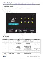
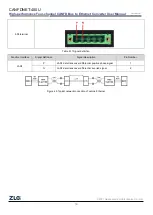
Figure 4.1 shows the device panel layout.
Figure 4.1 Panel layout
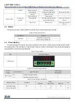
4.2 Indicators
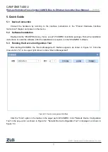
Table 4.1 LED indicators
Identification
Function
Status
Status Description
Flash description
PWR
Power indicator
Light off
The device is not powered on
-
Red
The device is powered on properly
-
SYS
System indicator
Green flashing light
System running
100 ms cycle, after ON
twice, wait for 500 ms
Always red
Device reset and restart
-
LAN0
Ethernet indicator
Light off
Ethernet no connected
-
Green normally on
Ethernet connected
-
Green flashing
The application has data
transmission and reception
Flash at an interval of
200 ms
Flash in red
Received data parsing error
Flash at an interval of
200 ms
LAN1
Vehicle Ethernet
Light off
Ethernet no connected
-

