CANFDNET-400U
High-performance Four-channel CANFD Bus to Ethernet Converter User Manual
©2021 Guangzhou ZLG Electronics Co., Ltd.
9
User Manual
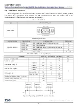
Balanced transmission is adopted for the CANFD bus . According to ISO11898-2: In the high-speed CANFD,
a 120 ohm terminal resistor needs to be connected to the network terminal node to eliminate signal reflection on
the bus and avoid signal distortion. Figure 4.2 shows the high-speed CANFD network topology.
The device has a built-in 120 ohm terminal resistance, which can be connected or disconnected through the
network configuration tool in ZCANPRO. For operation details, see chapter 5.5.2.
Note: The bus communication distance and communication rate are related to the field application and can
be designed according to the actual application and related standards. CANFD-Bus cable can be ordinary twisted
pair, shielded twisted pair or standard bus communication cable. In long-distance communication, the terminal
resistance value needs to be selected according to the communication distance, cable impedance and number of
nodes.
4.6 Ethernet Interface
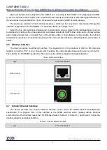
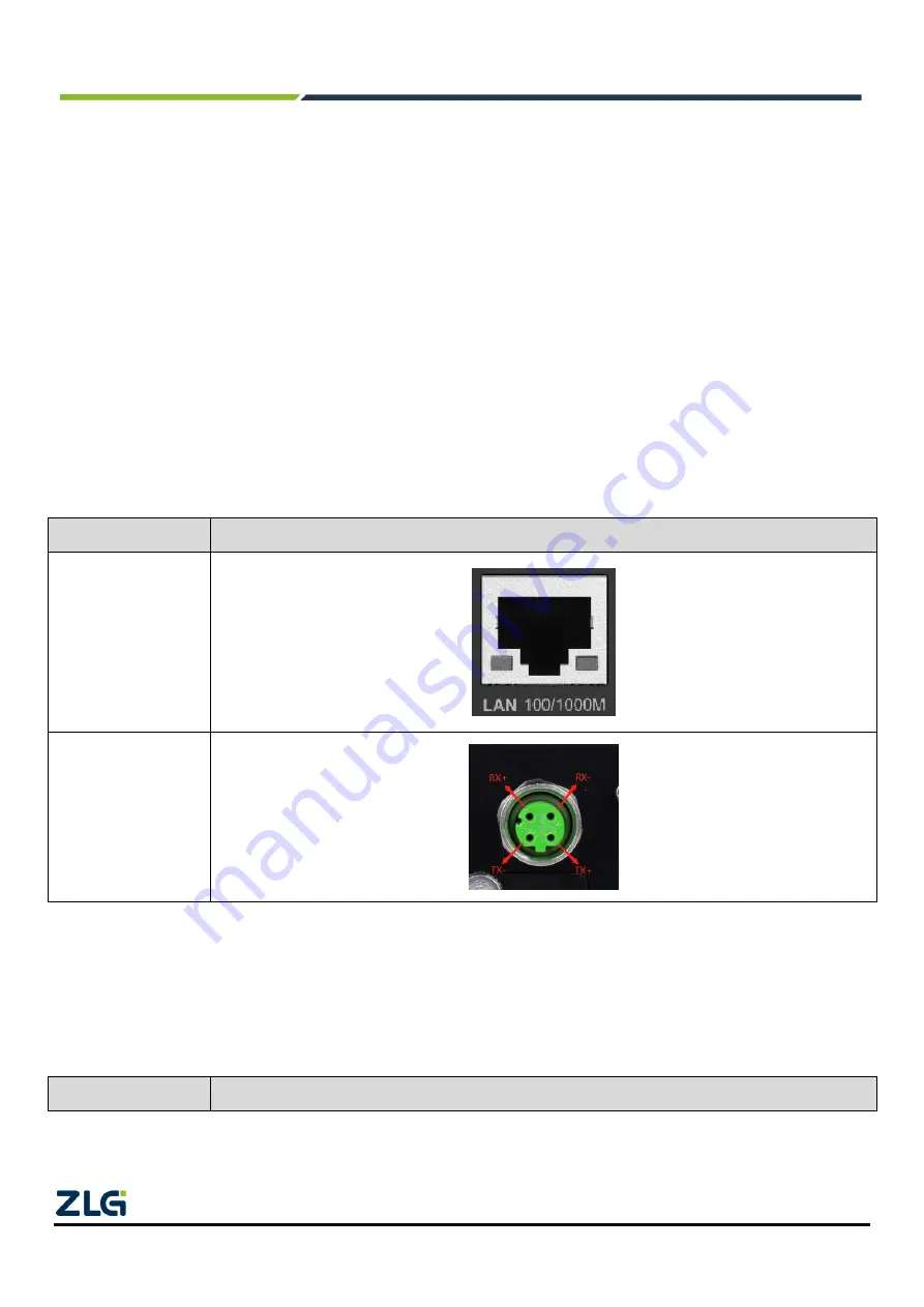
The device provides one Ethernet interface. The physical form of the interface is RJ45 or M12 terminal
(parallel connection, PHY is one channel), which realizes the communication between the device and the PC.
The interface is 100/1000M specification. Table 4.9 lists the interface diagram and signal definition.
Table 4.9 Ethernet interface
Type
Schematic Diagram
RJ45 terminal
M12 terminal
4.7 Vehicle Ethernet Interface
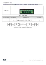
The device provides one vehicle Ethernet interface, which meets the OPEN Alliance BroadR-Reach
specification. The physical form of the interface is the OPEN terminal, which realizes vehicle Ethernet
communication. This interface meets the 10/100M specification. Table 4.10, Table 4.11, and Figure 4.3 show the
interface diagram and signal definition.
Table 4.10 Vehicle Ethernet interface
Type
Schematic Diagram

