15
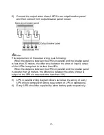
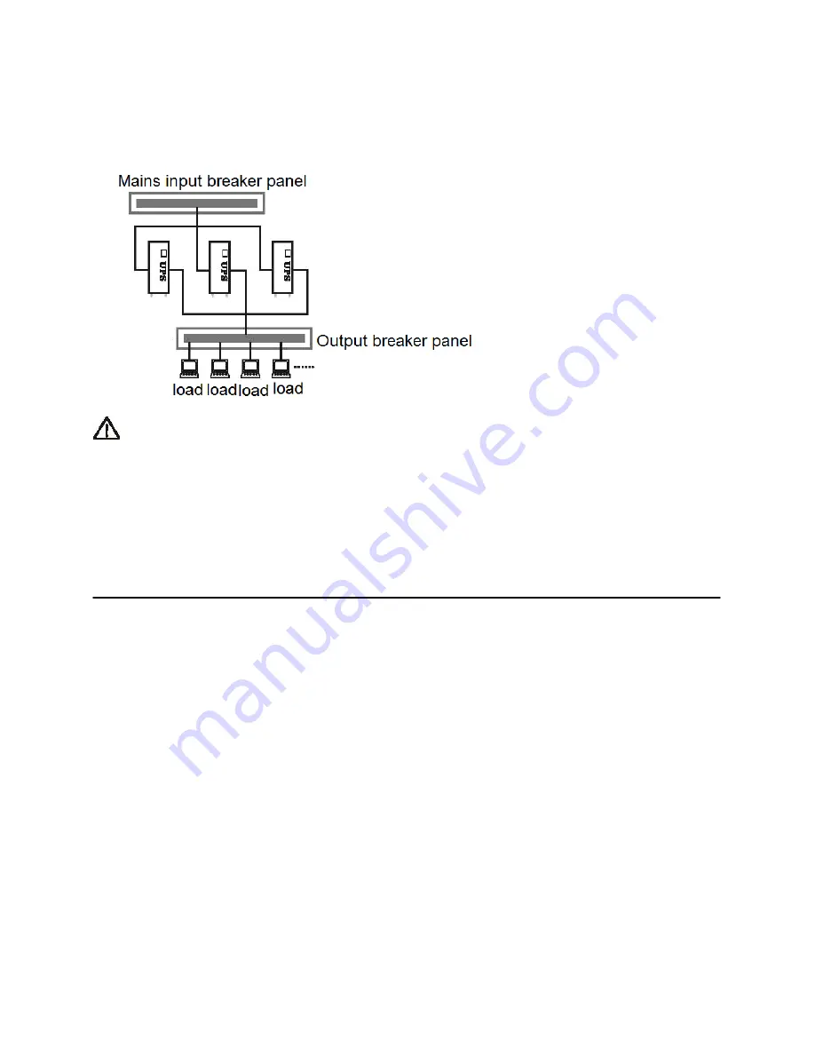
2) Connect the output wires of each UPS to an output breaker panel,
and then connect from output breaker panel to load.
Note:
The requirement of the output wiring is as following:
When the distance between the UPSs in parallel and the breaker panel
is less than 20 meters, the difference between the wires of input & output
of the UPSs is required to be less than 20%;
When the distance between the UPSs in parallel and the breaker panel
is greater than 20 meters, the difference between the wires of input &
output of the UPSs is required to be less than 10%.
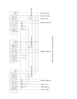
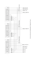
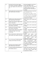
3) UPS in parallel wiring diagram shows as below, the wiring of every
UPS should comply with wiring requirement of UPS in standalone,
4) Every UPS should be supplied by alone battery pack respectively
Summary of Contents for EX series
Page 1: ...EX SERIES EX6K L EX10K L EX3110K L EX3115K L EX3120K L USER MANUAL...
Page 8: ...4 1 2 Front View 1 3 Rear View EX6KL EX10KL EX6K EX10K EX3110KL EX3115KL EX3120KL EX10K EX6K...
Page 9: ...5 EX6KL EX10KL EX3110KL EX3115KL EX3120KL...
Page 20: ...16...
Page 21: ...17...
Page 25: ...21...
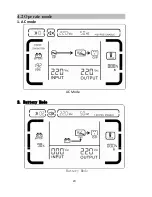
Page 33: ...29 4 2 Operate mode 1 AC mode AC Mode 2 Battery Mode Battery Mode...
Page 34: ...30 3 Standby Mode Standby Mode 4 Bypass Mode Bypass Mode...


