background image

ECI1000 Network Motion Control Card Hardware Manual Version1.4 

14


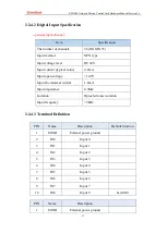
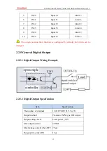
IN9 

Input 9   

Latch R1 

IN10 

Input 10 


IN11 

Input 11 


IN12 

Input 12 


IN13 

Input 13 


IN14 

Input 14 


IN15 

Input 15 


IN16 

Input 16 


10 

IN17 

Input 17 


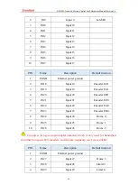
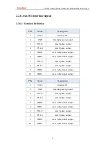
PIN   

Name 

Description 

Default function 

EGND 

External power ground   


IN18 

Input 18 

Encoder EZ1 

IN19 

Input 19 

Encoder EA1 

IN20 

Input 20 

Encoder EB1 

IN21 

Input 21 

Encoder EZ0 

IN22 

Input 22 

Encoder EA0 

IN23 

Input 23 

Encoder EB0 

IN24 

Input 24 

Home 0 

IN25 

Input 25 

Home 1 

10 

IN26 

Input 26 

Home 2 

  Encoder is low-speed optocoupler isolation, which is only used for handwheel 

and other low-speed 24V encoders, and the max frequency can’t exceed 5kHz. 
 

PIN   

Name 

Description 

Default function 

EGND 

External power ground   


IN27 

Input 27 

Home 3 

IN28 

Input 28 

Limit 0+ 

IN29 

Input 29 

Limit 0- 
Summary of Contents for ECI1000

Page 1: ...ECI1000 Network Motion Control Card Hardware Manual Version1 4 1 ECI1000 Network Motion Control Card Hardware Manual Version 1 4...

Page 2: ...well as the introduction and routines of each instruction please refer to ZBASIC software manual Information contained in this manual is only for reference Due to improvements in design and functions...

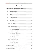
Page 3: ...1 2 2 3 RS232 Interface 12 2 2 4 General Input Signal 12 2 2 4 1 Digital Input Wiring Example 12 2 2 4 2 Digital Input Specification 13 2 2 4 3 Terminal Definition 13 2 2 5 General Digital Output 15 2...

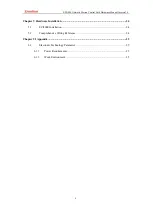
Page 4: ...are Manual Version1 4 4 Chapter V Hardware Installation 24 5 1 ECI1000 Installation 24 5 2 Comprehensive Wiring Reference 24 Chapter VI Appendix 25 6 1 Electronic Technology Parameter 25 6 1 1 Power R...

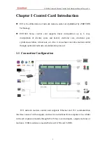
Page 5: ...helical electronic cam electronic gear synchronous follow virtual axis etc Also it can achieve real time motion control through optimized network communication protocol 1 1 Connection Configuration E...

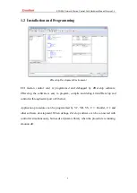
Page 6: ...y ZDevelop software ZDevelop the software is easy to program compile and debug Link ZDevelop and controller through serial port or Ethernet Application procedures can be programmed by VC VB VS C Build...

Page 7: ...ts can reach 512 through CAN The positive or negative limit signal origin signal of axis can be configured to any inputs The output current can reach 300mA which can directly drive some kinds of solen...

Page 8: ...e first 2 channels support large current the input can be one channel 24V encoder Max extended IO Up to 256 inputs and 256 outputs Internal ADDA No Max extended AD DA 128 ADs 64DAs Pulse bit 32 Encode...

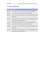
Page 9: ...ear interpolation circular interpolation ECI1308 3 axes point to point electronic cam linear interpolation circular interpolation continuous interpolation ECI1400 4 axes point to point electronic cam...

Page 10: ...xis through expansion module ECI1000 has 36 general inputs and 12 general outputs the first two channels are large current output ECI1000 has one RS232 serial port and one Ethernet interface ECI1000 s...

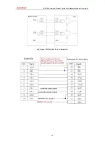
Page 11: ...fferential data CAN bus of ECI1000 uses internal power When multi controllers are linked on CAN bus it is necessary to connect 120 resistor between CANL and CANH of the last IO expansion module For CA...

Page 12: ...PIN NO Name Description 2 RXD Receive data PIN 3 TXD Send data PIN 5 GND Internal power ground 9 DC5V Power 5V output it supplies text screen 2 3 crossover cable with two female head is needed when t...

Page 13: ...nt typical value 4 8mA Input open voltage 14 5V Input the minimal current 1 8mA Input impedance 4 7K Isolation Optoelectronic isolation Input frequency 5kHz 2 2 4 3 Terminal Definition PIN Name Descri...

Page 14: ...der EZ1 3 IN19 Input 19 Encoder EA1 4 IN20 Input 20 Encoder EB1 5 IN21 Input 21 Encoder EZ0 6 IN22 Input 22 Encoder EA0 7 IN23 Input 23 Encoder EB0 8 IN24 Input 24 Home 0 9 IN25 Input 25 Home 1 10 IN2...

Page 15: ...e origin position limit function is configured by default but which can be changed 2 2 5 General Digital Output 2 2 5 1 Digital Output Wiring Example 2 2 5 2 Digital Output Specification Item Specific...

Page 16: ...f resistance load and it will change when the load circuit changed 2 2 5 3 Output 0 5 PIN Name Description 1 24V 24V power output 2 EGND External power ground 3 OUT0 Output 0 4 OUT1 Output 1 5 OUT2 Ou...

Page 17: ...l output 6 DIR0 Axis 0 directional output 7 PUL1 Axis 1 pulse output 8 PUL1 Axis 1 pulse output 9 DIR1 Axis 1 directional output 10 DIR1 Axis 1 directional output PIN Name Description 1 VCC5 Internal...

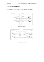
Page 18: ...CI1000 Network Motion Control Card Hardware Manual Version1 4 18 2 2 6 2 Axis Wiring Reference 2 2 6 2 1Wiring Reference for Low speed Differential Pulse Differential Connection Single ended Connectio...

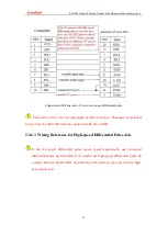
Page 19: ...sonic economical servo now the 2th GND must be connected with drive GND 2 2 6 3 Wiring Reference for High speed Differential Pulse Axis If the low speed differential pulse meets speed requirement use...

Page 20: ...ECI1000 Network Motion Control Card Hardware Manual Version1 4 20 High speed Differential Pulse Connection...

Page 21: ...y in actual application ZIO power channels on expansion modules can share the same power supply the IO power supply of the E24V of the IO board is powered separately When the control card and expansio...

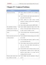
Page 22: ...e and motor is correct and whether connection between the drive and the controller is correct Check whether the drive works properly and there is no alarm Motor can rotate but it is not working normal...

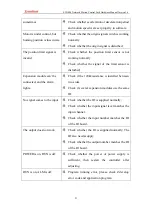
Page 23: ...be connected and the alarm lights Check if the 120 resistance is installed between two sides Check if several expansion modules use the same ID No signal comes to the input Check whether the IO is sup...

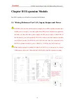
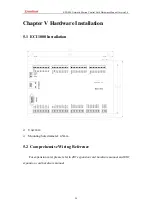
Page 24: ...Version1 4 24 Chapter V Hardware Installation 5 1 ECI1000 Installation Unit mm Mounting hole diameter 4 5mm 5 2 Comprehensive Wiring Reference For expansion card please refer to ZIO expansion card har...

Page 25: ...Technology Parameter 6 1 1 Power Requirements Item Parameter Power voltage It is recommended to set DC24V the max value can be 18V 36V Current when open 0 5A DC24V Current when work 0 4A DC24V 6 1 2...

Reviews: