VPLCE532E Vision Motion Controller User Manual V1.5
system, this connection also can be omitted.
3.4.2.
Basic Usage Method
(1)
Please follow the above wiring instructions to wiring correctly.
(2)
After powered on, please select LAN1, LAN2, RS232 or RS485 to connect to ZDevelop.
(3)
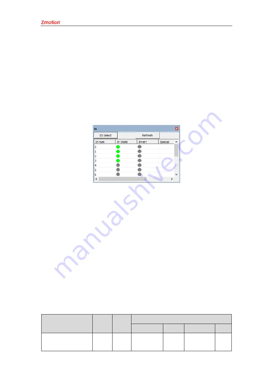
State values of relative input ports
can be read directly through “IN” command, also,
it can be read through “ZDevelop/View/In”. Please refer to “ZBasic” for details.
(4)
Latch function can be set and triggered
through “REGIST” instruction, in software,
use REG_INPUTS to configure. Please refer to “ZBasic” for details.
3.5.
OUT Digital Output & PWM & Hardware Comparison
Output & Single-ended Pulse
The digital output adopts a group of screw-type pluggable terminals with a spacing
of 3.81mm, and the PWM, single-ended pulse and hardware comparison output functions
are integrated in digital output signals.
→
Terminal Definition
Terminal
Name
Type
Functions
1
2
3
4
EGND
/
E5V power
ground / IO
/
/
/
Summary of Contents for VPLC532E
Page 1: ......
Page 39: ...VPLCE532E Vision Motion Controller User Manual V1 5...


