VPLCE532E Vision Motion Controller User Manual V1.5
→
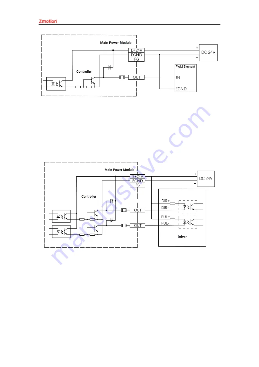
Pulse Wiring
Here, use OUT0 and OUT1 to connect to driver, when wiring is done, when OUT0 and
OUT1 are configured through ATYPE (6) = 1. OUT 0 is PUL6, OUT1 is DIR6, and
corresponding pulse driver axis No. is 6.
E24V or E5V can be used according to specific driver.
→
Wiring Note:
⚫
The wiring principle of high-speed digital output OUT (0-3) and low-speed digital
output OUT (4-11) is shown in the figure above. The external signal receiving end can
be an optocoupler or a relay or solenoid valve, all can be connected as long as the
input current does not exceed 300mA.
⚫
For the connection of the public end, please connect the "EGND" port on the IO
terminal to the negative pole of the DC power supply of the external input device. If
the DC power supply of the external device and the controller power supply are in the
Summary of Contents for VPLC532E
Page 1: ......
Page 39: ...VPLCE532E Vision Motion Controller User Manual V1 5...


