XPLC108E Motion Controller User Manual V1.5
Chapter III Wiring, Communication
Configuration
3.1.
Power Input, CAN Communication Interface
The power supply input adopts a 5Pin (there are all 5 terminals) screw-type pluggable
wiring terminal, and the interval (means the gap distance between two ports) should be
3.81mm. This terminal is the power supply of the controller, and it is shared with CAN
communication at the same time.
→
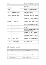
Main Power Terminal Definition:
Terminal
Name
Type
Function
+24V
Input
Power 24V input
CANH Input/output
CAN differential data +
EARTH
Grounding
Shield
CANL Input/output
CAN differential data -
GND
Input
Power ground
Note: please supply internal 24V power and external 24V IO power separately, it is not
recommended to use one same power supply, or use one power that provides 2
isolated 24V.
→
IO Power Terminal Definition:
Terminal
Name
Type
Function
EGND
Input
IO power ground
E24V
Input
Power 24V input
Note: please supply internal 24V power and external 24V IO power separately, it is not
recommended to use one same power supply, or use one power that provides 2
isolated 24V.
Summary of Contents for XPLC108E
Page 1: ......


