XPLC108E Motion Controller User Manual V1.5
(5)
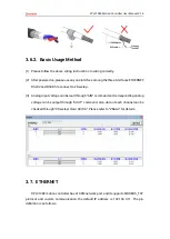
After all the settings are completed, restart the power supply of all stations to
establish communication.
(6)
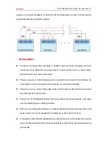
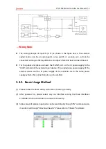
Note that the "speed" settings of each node on the CAN bus must be consistent, and
the "address" settings cannot cause conflicts, otherwise the "ALM" alarm light will be
on, and the communication establishment will fail or the communication will be
disordered.
3.2.
RS485 Serial Port
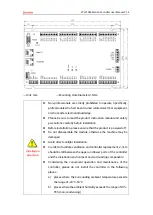
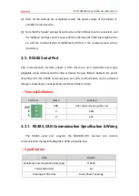
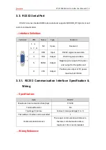
The communication interface adopts a 5Pin (there are all 5 terminals) screw-type
pluggable wiring terminal, and the interval (means the gap distance between two ports)
should be 3.81mm. RS485 communication and CAN communication can be achieved
through connecting to corresponding interfaces of this terminal.
→
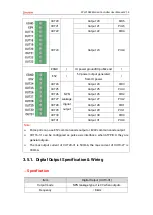
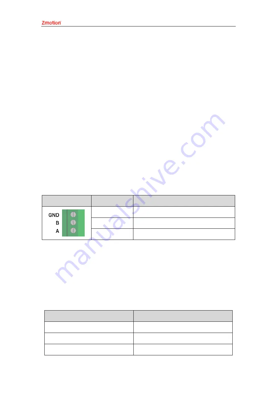
Terminal Definition:
Terminal
Name
Function
GND
485 communication public end
A
485+
B
485-
3.2.1.
RS485, CAN Communication Specification & Wiring
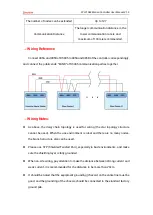
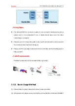
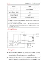
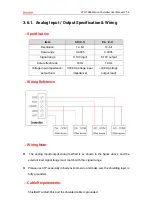
The RS485 serial port supports the MODBUS_RTU protocol and custom
communication, mainly including 485A, 485B and public end.
→
Specification
Item
RS485
Maximum Communication Rate (bps)
115200
Terminal Resistor
No
Topological Structure
Daisy Chain Topology
Summary of Contents for XPLC108E
Page 1: ......

