ZMC408SCAN Motion Controller Hardware Manual V1.5
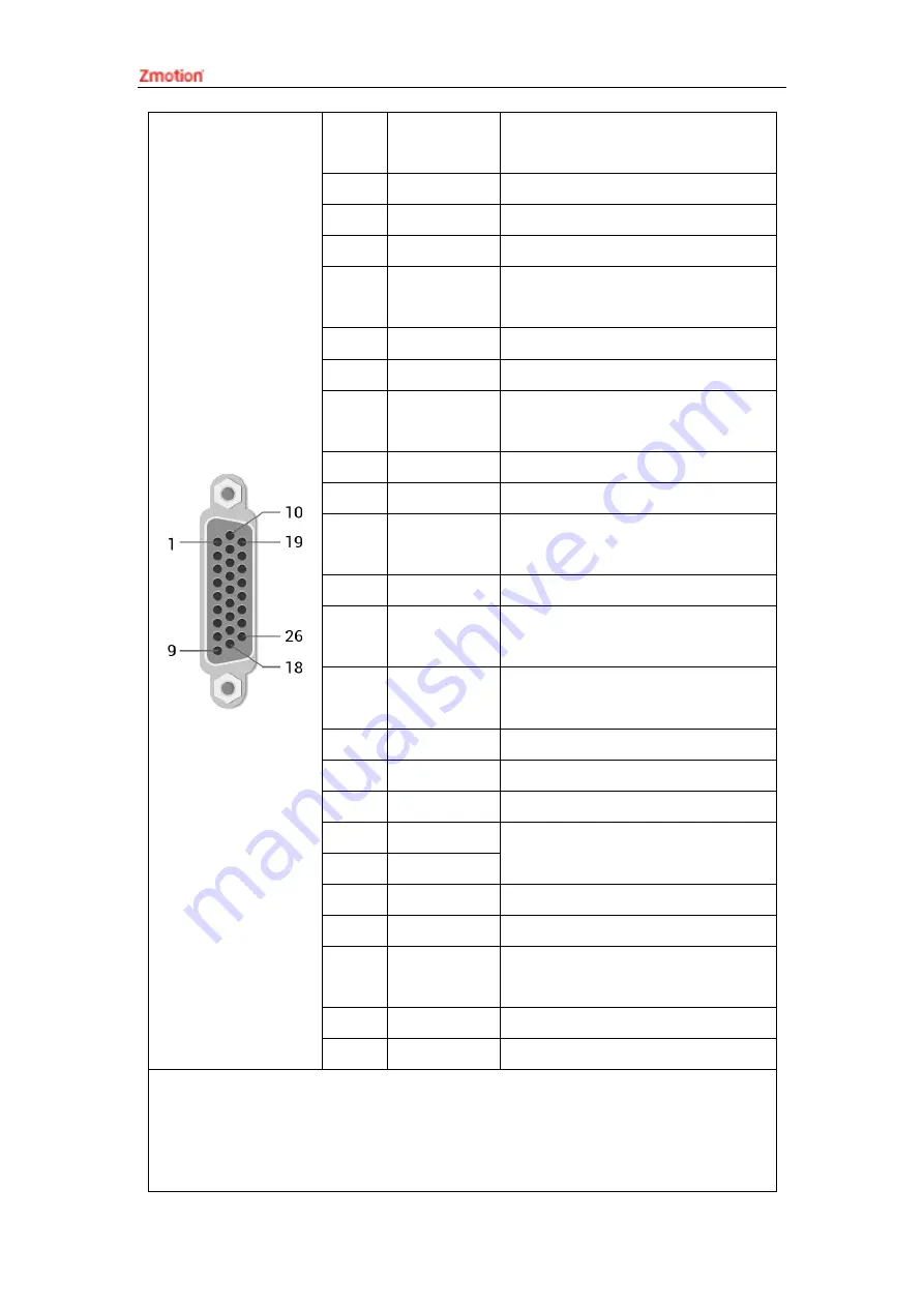
3
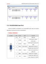
OUT20-
2317ENABLE
General output (recommended as
driver enable)
4
EA-
Encoder differential input signal A-
5
EB-
Encoder differential input signal B-
6
EZ-
Encoder differential input signal Z-
7
+5V
Positive pole of 5V power of
pulse/encoder signal
8
Reserved
Reserved
9
DIR+
Servo or step direction
10
GND
Negative pole of 5V power of
pulse/encoder signal
11
PUL-
Servo or step pulse output -
12
Reserved
Reserved
13
GND
Negative pole of 5V power of
pulse/encoder signal
14
OVCC
Positive pole of IO 24V power
15
OUT24-
27/CLR
Digital output, recommended as
drive alarm clearing
16
IN28-31/INP
Digital input, recommended as on-
position signal
17
EA+
Encoder differential input signal A+
18
EB+
Encoder differential input signal B+
19
EZ+
Encoder differential input signal Z+
20
GND
Negative pole of 5V power of
pulse/encoder signal
21
GND
22
DIR-
Servo or step direction output -
23
PUL+
Servo or step pulse
24
GND
Negative pole of 5V power of
pulse/encoder signal
25
Reserved
Reserved
26
Reserved
Reserved
Note:
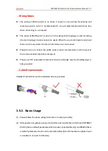
ALM, ENABLE, CLR and INP are recommended to be used as axis IO, because the
drive capacity is small.
OVCC, +5V are only used for communication between the controller and the

