ZMC408SCAN Motion Controller Hardware Manual V1.5
Chapter V LASER Interface
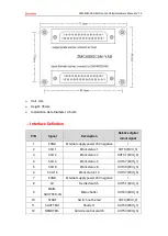
This product provides one interfaces specialized for local YLR laser, and interface is
double-row standard DB25 male socket
⚫
The LASER laser control interface supports the connection of IPG, YLR, YLS and other
types of lasers.
⚫
The laser can be operated by sending output signals such as laser, red light, and
enable through the direct controller to make the laser respond accordingly.
⚫
There are 2 PWM output ports in the DB interface, corresponding to OUT8 and OUT9.
⚫
It can receive laser signal, display IN signal and respond accordingly.
→
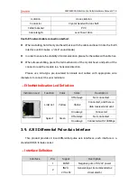
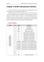
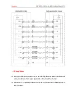
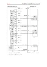
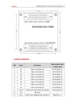
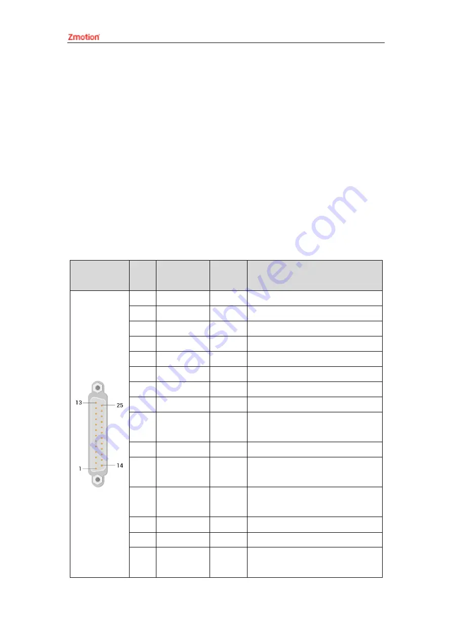
Wiring Notes
Interface
PIN
Signal
Operate
port
Description
1,4,14
LAGND
LAGND
Laser analog signal reference ground
2,3,13
NC
Reserved
5
Guide Control
OUT32
Red light control output pin, 24V is valid
6
ACON
OUT33
Reserve output pin, 24V is valid
7
LaserRequest
OUT28
Laser request output, 24V is valid
8
Program start
OUT29
Program start output, 24V is valid
9
ERST
OUT30
Laser reset output, 24V is valid
10
LASER ON
OUT31
Laser enable output, 24V is valid
11
PWM/NC
OUT9
Reserve PWM signal, 24V electric level,
special modes are valid
12
Modulation-
/
Modulate signal -
15
LASER_AD/NC
AIN(2)
Reserve analog input, 0-10V, 16-bit
resolution, special modes are valid
16
LASER_DA/NC
AOUT(2)
Reserve analog output, 0-10V, 16-bit
resolution, special modes are valid
17
Error
IN44
Laser alarm input, 24V is valid
18
Emission EN
IN45
Laser emission input, 24V is valid
19
Pow Active
IN49
Laser main power has opened, 24V is
valid


