ZMC416BE Motion Controller User Manual V1.5
Isolation mode
Optical isolation
Optical isolation
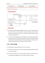
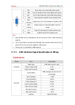
Note: the above parameters are standard values when the controller power supply
voltage (E+24V port) is 24V.
→
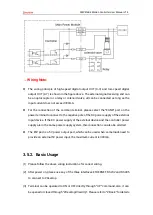
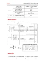
Wiring Reference
→
Wiring Note:
⚫
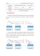
The wiring principle of high-speed digital input IN (0-1) and low-speed digital input
IN (2-23) is shown in the figure above. The external signal source can be an
optocoupler or a key switch or sensor, etc., all can be connected as long as the output
level meets the requirements.
⚫
For the common terminal, please select the "EGND" port on the power supply terminal
to connect to the "COM" terminal of the external input device. If the power supply of
the signal area of the external device and the power supply of the controller are in the
same power supply system, this connection can also be omitted.
3.4.2.
Basic Usage
(1)
Please follow the above wiring instructions for correct wiring.
(2)
After power on, please use any of the three interfaces ETHERNET, RS232 and RS485
to connect to ZDevelop.
(3)
State values of relative inputs can be read directly through “IN” command, also, it can
be read through “ZDevelop/View/In”. Please refer to “ZBasic” for details.
Summary of Contents for ZMC416BE
Page 1: ......

