ZMC416BE Motion Controller User Manual V1.5
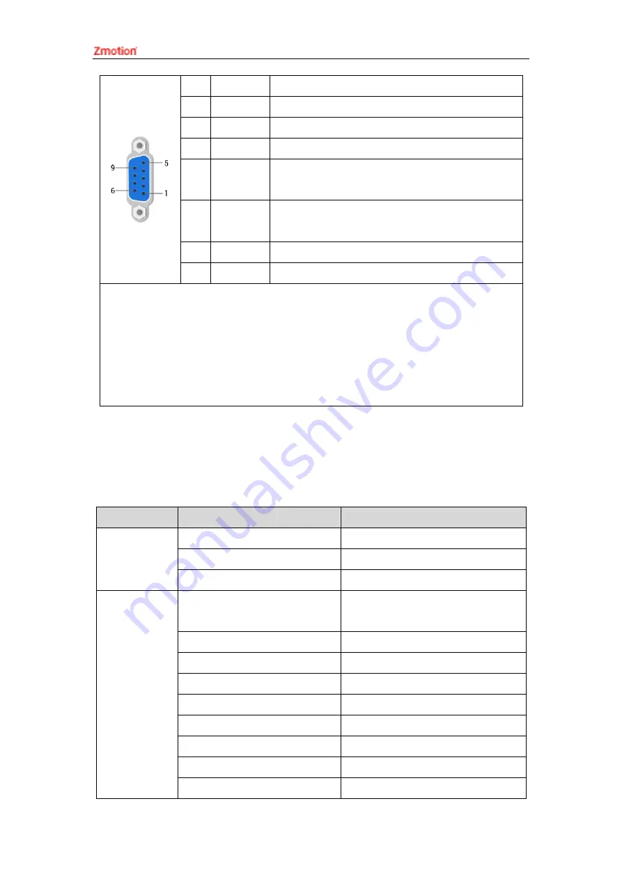
2
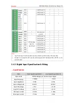
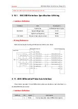
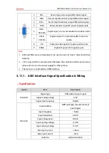
PUL-
Servo/step pulse output differential signal -
3
DIR+
Servo/step directional output differential
4
DIR--
Servo/step directional output differential signal -
5
GND
Pulse/encoder signal 5V power negative pole
6
IN24-
28/ALM
Digital input, it is recommended to do drive alarm
7
OUT8-
22/ENA
Digital output, it is recommended to do drive
enable
8
+5V
Pulse/encoder signal 5V power positive pole
9
EGND
Digital IO power 24V negative pole
Note:
ALM and ENA are recommended to be used as axis IO due to their small drive
capacity.
+5V is only used for communication between the controller and the servo driver,
please do not use it as power supply for other places.
The last axis is controlled by PWM interface.
3.11.1.
AXIS Interface Signal Specification & Wiring
→
Specification:
Signal
Item
Description
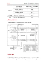
PUL/DIR
Signal type
Differential output signal
Signal voltage range
0-5V
Signal max frequency
10MHz
IN24-38
Input method
NPN leak type, low electric level
input trigger
Input frequency
<
5kHz
Input impedance
6.8KΩ
Input voltage level
DC24V
Input opening voltage
<10.5V
Input closing voltage
>10.7V
Min input current
-1.8mA
Max input current
-4mA
Isolation
Optical isolation
Summary of Contents for ZMC416BE
Page 1: ......

