Page 19
Page 18
Clearwater Duo™, eXO
®
| Installation Manual
Section 8. Installing and Assigning
Equipment
8.1 Filter Pump
Both single and variable speed pumps can be
connected to and operated by the controller.
8.1.1
Single Speed Filter Pump
NOTE:
For any manually-operated variable speed pump
(i.e., any pump that does not have an RS485
communication cable), you must set the pump
configuration to single speed.
1. Disconnect power from the chlorinator and
remove the cover and lower housing.
2. Connect the filter pump to the controller at
the pump connection point in the high voltage
raceway. For Australian installations plug the
filter pump into the socket provided on the
underside of the control unit see Table 5 and
Figure 10 for wiring details.
3. Replace the lower housing and cover.
4. Plug the pump into the socket in the base of
the chlorinator.
8.1.2
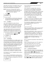
Assign Single Speed Pump
1. Press
.
2. Use
to select “Filter Pump”
then press .
3. Use
to select “Single Speed”
then press .
4. The user interface will prompt “Single Speed
Plugd to Device”. Use
to select “Yes”
then press .
<
-FILTER PUMP
-AUX/LIGHTS
-PROGRAMMING
-LOW MODE
-SLAVE MODE
-REVERSING
-HELP MENU
-LANGUAGE
MAIN MENU
<
-BACKWASH
-SINGLE SPEED
-VARIABLE SPEED
FILTER PUMP
<
PLUGD TO DEVICE?
-YES
-NO
SINGLE SPEED
8.1.3
Variable Speed Filter Pump
The following pump models are compatible:
FloPro™ VS, Flopro™ VS AUT
NOTE:
Not compatible with Zodiac e3 1Hp pump, or any
any other manually-operated variable speed pump
that does not have an RS485 communication cable;
is compatible with e3 1.5Hp pump, which features
RS485 compatibility
.
1. Disconnect power from the chlorinator and
remove the cover and lower housing.
2. Connect the filter pump to the controller at
the VSP RS485 connection point in the low
voltage raceway, see Table 5 and Figure 10 for
wiring details.
3. Remove the single screw on the rear hatch
of the VS pump to access the red 4-pin
connector and communication cable.
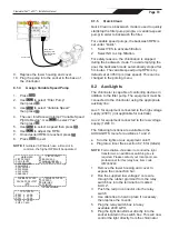
If the On Board Controller is connected to the
RS485, remove it and set it next to the hatch.
Remove the ‘on board’
controller red 4 pin
connector
4. Feed the cable with red pin connector through
the cable gland hole and push onto the four
pins on the pump PCB.
5. Run the cable from the VS pump through the
soft membrane under the chlorinator housing
(pierce with a screwdriver).
Pierce hole thru the soft
membrane to run the 4 core cable
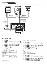
6. Strip a few cm of bare wire from the 4 core
cable and connect the cable to the low voltage
section marked ‘VSP RS485’.
7. Ensure the RS485 wires are in the proper order.
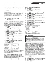
8. Ensure the pump DIP switches are in the
correct position as follows:
1 = up
2 = up
3 = down
4 = down
5 = up
LOW VOLTAGE
HIGH VOLTAGE
RED
BL
K
YE
L
GRN
On the Controller
RED BL
K
YE
L
GRN
On the Pump
NOTE:
Do not change the position of the dip switches
on the pump.


