


Page 12
ENGLISH
Zodiac
®
Sheer Descent
®
and Fiberfall
®
Water Features
|
Installation and Operation Manual
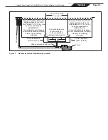
When plumbing a pump dedicated for use by the Sheer
Descent, a separate suction line to the pool must be
plumbed. This should be plumbed in a minimum of 2
inch schedule 40 pipe.
WARNING
The suction outlet (drain) assembly and its cover
must comply with the latest version of ANSI/ASME
A112.19.8, the standard for Suction Fittings For Use
in Swimming Pools, Wading Pools, Spas, and Hot
Tubs, or its successor standard, ANSI/APSP-16.
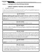
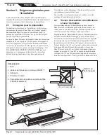
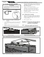
A Sheer Descent filter/strainer (p/n 3456), or equivalent,
must be installed on the return side of the pump,
between the pump and the waterfall. Refer to Figure 11.
FILTER IS REQUIRED for separate pump installations,
as large debris must not be allowed to enter the waterfall
unit. For installations requiring up to 60 gallons (227 l)
per minute, use one Sheer Descent filter/strainer. For
higher water requirements, use two or more filters
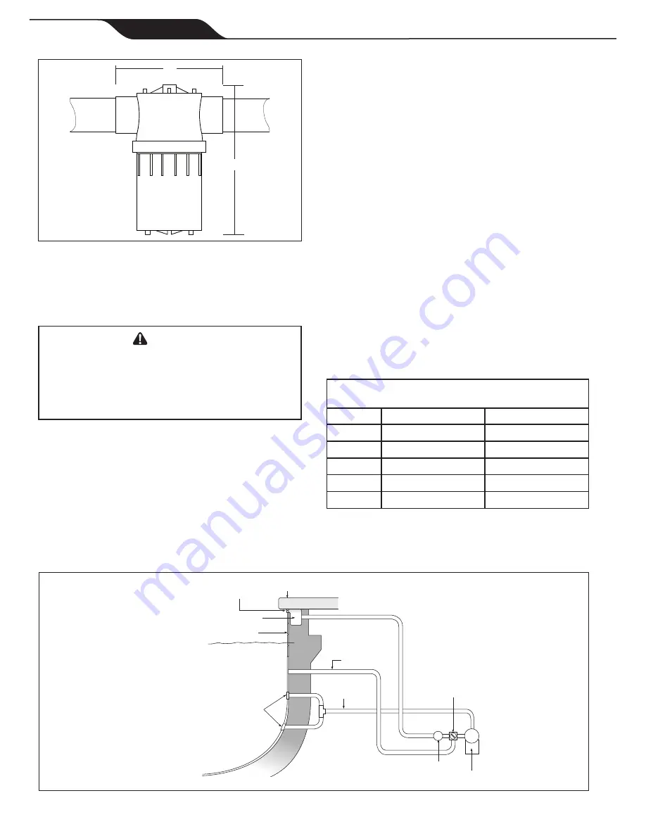
plumbed in parallel. A separate return line, with a three
way valve plumbed in such a way that water can be
NOTE: At least two (2) (anti-entrapment)
suction outlets provided with covers
which are listed/certified as complying
with ANSI/ASME A112.19.8-2007 or its
successor standard, ANSI/APSP-16.
Suction outlets (drains) should be
installed in accordance with
ANSI/APSP-7, the American National
Standard for Suction Entrapment
Avoidance in Swimming Pools, Wading
Pools, Spas, Hot Tubs, and Catch Basins.
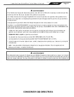
Suction Line
Separate Return
to Pool
Jandy
®
Three Way Valve
Sheer Descent
Filter/Strainer Filter
Pump
Water Line
Sheer Descent Unit
Conventional
Concrete Decking
Tile
Cantilever Edge
Figure 12. Filter Pump Installation
Figure 11. Sheer Descent Filter/Strainer (p/n 3456)
7”
9 3/4”
balanced between the waterfall and return back to the
pool, is also required. See Figure 12.
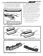
Section 4. Plumbing the Sheer
Descent Waterfall
4.1 Waterfall Return Line Plumbing
NOTE
If the waterfall flow rate exceeds more that
40% of the filtration flow, a separate pump is
recommended.
T
he waterfall feed line, from either the main filter pump
or a separate pump, should be plumbed with a pipe
size capable of handling the required flow rate of the
waterfall. See Table 1.
NOTE Two inch plumbing or larger is suggested for
waterfalls over 5 feet in total length. Refer
to Hydraulic Guideline Chart, Table 1, for
specifications. The feed line should end near
the back of the bond beam near the center of
the waterfall location.
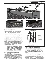
Table 1. Hydraulic Guideline Chart
Suction (SUC) and Discharge (DIS)
Water Flow Chart for PVC
Pipe Size
Max SUC Flow*
Max DIS Flow**
1½”
37 gpm (140 lpm)
50 gpm (189 lpm)
2”
62 gpm (235 lpm)
82 gpm (310 lpm)
2½”
88 gpm (333 lpm)
117 gpm (443 lpm)
3”
136 gpm (515 lpm)
180 gpm (681 lpm)
4”
234 gpm (886 lpm) 313 gpm (1185 lpm)
* Max SUC Flow based on 6 feet (1.8 m) per second velocity.
** Max DIS Flow based on 8 feet (2.4 m) per second velocity.
It is important to have a valve located in a convenient
location on the feed line to regulate the flow of water to


