


Page 14
ENGLISH
Zodiac
®
Sheer Descent
®
and Fiberfall
®
Water Features
|
Installation and Operation Manual
removed. Remember to leave enough room for tile and
thin set, so the deepest edge of the radius cut will not be
recessed from the tile line.
NOTE
Never remove more than 4” (10.2 cm) of the
extended lip, always leaving a minimum of 2”
(5.1 cm) of lip. See Figure 17.
Remove the lip protector prior to cutting the waterfall.
Remember to REPLACE THE LIP PROTECTOR after
cutting the radius to protect the fall from construction
debris.
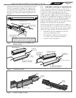
The waterfall must be cut with a coarse tooth saw
blade. Caution must be taken to make the cut as smooth
as possible to avoid a jagged edge. After cutting the
waterfall, insert the spacer removal tool (included in
product packaging) 1 inch (2.5 cm) into the waterfall
opening. Move the tool around the opening. If the tool
hits a support, use the notch in the tool to remove the
support. See Figure 18. Make sure all supports within
1 inch (2.5 cm) of lip opening are removed. DO NOT
LEAVE THE LOOSE SUPPORT SECTION IN THE
WATERFALL.
After removing sections of the supports, use a 1/8 inch
(0.32 cm) flat file and coarse grade sandpaper to smooth
the edges of the waterfall, follow with a fine grade of
sandpaper to get the edge as smooth as possible. A
sanding block is recommended to avoid rounding the
edges of the waterfall.
Insert the lip protector back into the opening and
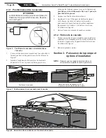
Figure 18. Custom Installations - Concave Radius
Concave Radius
2" (5.1 cm) minimum
Break off lip supports
1" (2.5 cm) from lip of waterfall
Support
removal tool
Insert Lip Protector
Concave Radius
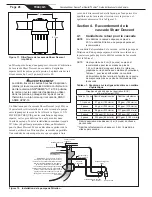
6"
(15.2 cm)
¾"
(1.9 cm)
¼"
(.64 cm)
½"
(1.3cm)
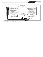
Figure 19. Extended Lip Radius Installation
Sheer Descent Waterfall
extended lip radius installation
Do not
remove more
than 4" (10.2 cm)
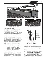
Figure 17. Custom Installations - Convex Radius
Convex Radius
Break off lip spacers
1" from lip of waterfall
Spacer
removal tool
Insert Lip Protector
Convex Radius
continue installation, following the installation
instructions for the standard Sheer Descent waterfall.
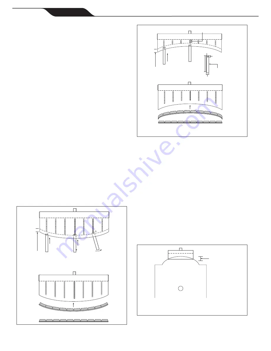
4.5 Sheer Descent Waterfall Radius Cut
Guideline
NOTE
Never remove more than 4” (10.2 cm) of the
extended lip, always leaving a minimum of 2”
(5.1 cm) of lip. The top of the beam, where the
Sheer Descent unit is to be installed, should
be a minimum of 9” (22.9 cm) thick. When
designing custom curves for the Sheer Descent
Extended Lip models, please refer to Table
2, for radius guidelines to select the correct
Sheer Descent model. Super Radius models
accommodate very tight radius curves and are
available by special order. Refer to Figure 19.


