background image

Overview 

740


SELECT


21-22-0335 Rev D


Page 4 of 40 


 CONVENTIONS USED IN THIS MANUAL 


Warning:

  Directions that warn of conditions that put the patient or the caregiver at risk.


Caution:

  Directions that help to avoid damaging the 

740


SELECT


monitor or losing data.


Note:

  Directions that make it easier to use the 

740


SELECT

 monitor.


IMPORTANT: 

Read the 

740


SELECT


User Manual, Zoe Medical PN 21-22-0316 carefully 

before patient use of the Monitor. 


This Manual addresses all optional ECG parameters of the 

740


SELECT


monitor. 


Read this Manual carefully before patient use of the Monitor. 


Zoe Medical reserves the right to make changes to this Manual and improvements to 

the product it describes at any time without notice or obligation. 


Copyright 

©

 2021 Zoe Medical.  All rights reserved 


REVISION HISTORY 

This Manual has a revision number located at the bottom of each page.  It changes whenever 
the Manual is updated. 


Rev A 

October 2015 


Rev B 

March 2019 


Rev C 

April 2020 


Rev D 

October 2021 


WARRANTY 

Refer to the 

740 

SELECT


User Manual, Zoe Medical PN 21-22-0316, for full Warranty Policy for 

Zoe Medical 

740 

SELECT


monitor.  In all cases, policy applies from date of purchase from Zoe 

Medical or its authorized distributors or agents. 

ECG Accessories:  

Out-of-box failure only 


Summary of Contents for 740 SELECT

Page 1: ...1 of 40 740 SELECT Multi Parameter Monitor User Manual Addendum ECG Resp Parameters This User Manual Addendum describes the features and operations of the 740 SELECT Multi Parameter monitor Software...

Page 2: ...ion of the trademarked name the publisher states that it is using the names only for editorial purposes and to the benefit of the trademark owner with no intention of improperly using that trademark i...

Page 3: ...SELECT 21 22 0335 Rev D Page 3 of 40 CONTACT ADDRESSES Zoe Medical Inc 460 Boston Street Topsfield MA 01983 U S A Phone 978 887 4013 Fax 978 887 1406 E Mail customersupport zoemedical com Web www zoe...

Page 4: ...nual carefully before patient use of the Monitor Zoe Medical reserves the right to make changes to this Manual and improvements to the product it describes at any time without notice or obligation Cop...

Page 5: ...PLACEMENT AHA 16 STANDARD PLACEMENT IEC 16 PLACEMENT FOR PACED PATIENTS AHA 17 PLACEMENT FOR PACED PATIENTS IEC 17 VERIFYING PROPER PACEMAKER HANDLING 18 FREEZING WAVEFORMS 18 ECG SETUP 19 ECG LEAD W...

Page 6: ...RR AUTO set ALARM LIMITS 29 TESTING RR ALARMS 30 RESPIRATION RATE MONITORING MESSAGES 31 5 ACCESSORIES 32 ECG AAMI 32 ECG IEC 33 6 DISPOSAL 34 ACCESSORIES 34 MONITOR 34 GUIDANCE 34 7 MAINTENANCE 35 EQ...

Page 7: ...URES Figure 1 ECG Patient Cable Receptacle on left side of Monitor 12 Figure 2 ECG Patient Cable connected on Monitor 13 Figure 3 ECG Lead Set connected on ECG Patient Cable Yoke 14 Figure 4 ECG Wavef...

Page 8: ...fessionals in all areas of a healthcare facility OVERVIEW OF HEART RATE MONITORING ECG Monitoring works through the sensing the electrical signals generated by the electrical activity of the heart as...

Page 9: ...ation Rate RR in respirations per minute Displaying the Respiration waveform continuously The same electrodes are used for both ECG and Respiration monitoring Note A 740 SELECT monitor configured with...

Page 10: ...may continue to count the pacemaker rate during occurrences of cardiac arrest Keep pacemaker patients under close surveillance and do not rely entirely upon Heart Rate alarms Warning ELECTROSURGERY Th...

Page 11: ...ipment is less than 10 microamperes uA The monitor applies approximately 2 uA to the patient CAUTIONS Caution Line isolation monitor transients may resemble actual cardiac waveforms and thus inhibit h...

Page 12: ...r Locate the ECG Patient Cable Receptacle on the side of the Monitor Refer to Figure 1 ECG Patient Receptacle on Monitor Receptacle key Figure 1 ECG Patient Cable Receptacle on left side of Monitor No...

Page 13: ...ECG Receptacle is keyed so that the ECG Patient Cable can only be inserted into the monitor in one orientation The key on the ECG Patient Cable Receptacle is located towards rear of monitor ECG Patie...

Page 14: ...3 Select and prepare the electrodes Pregelled Ag AgCl disposable electrodes are recommend Depending on the situation you may want to use either the short term foam backed or long term cloth backed el...

Page 15: ...en The ECG and Heart Rate Monitoring settings and specifications may be found in the SPECIFICATIONS chapter of this manual Procedures for changing configuration settings such as sourcing pulse rate PR...

Page 16: ...ow the clavicle 3 Position the left leg LL electrode on the left mid clavicular line 6th and 7th intercostal space STANDARD PLACEMENT IEC For ECG cable lead sets with IEC Europe lead designations posi...

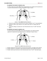
Page 17: ...le 3 Position the left leg LL electrode on the left mid clavicular line 6th and 5th intercostal space PLACEMENT FOR PACED PATIENTS IEC For ECG cable lead sets with IEC Europe lead designations the opt...

Page 18: ...his manual FREEZING WAVEFORMS In some clinical environments the user may want to freeze the displayed waveforms Touching the right side of the waveform area under the blue line will cause all displaye...

Page 19: ...OK and c Touch Home to return to the Main screen Figure 10 ECG Waveform Setup screen ECG SIZE a Touch the left side of the waveform area b Touch the adjacent to the Waveform 1 Size selection c Touch...

Page 20: ...ECG CASCADE i Touch the left side of the waveform area j Touch the Yes adjacent to the ECG Cascade selection to Enable OR k Touch the No adjacent to the ECG Cascade selection to Disable l Touch Home t...

Page 21: ...ll not generate any visual or audible indication of an alarm condition for HR 3 Adjust the desired HR Upper or Lower Limit value The HR Upper and Lower Alarm Limits can be adjusted independently 4 Tou...

Page 22: ...labeled HR Note If during Alarm Pause condition a High Priority alarm occurs Asystole or HR Ventricular Fibrillation the Alarm Pause condition will be exited and the High Priority Alarm shall be annu...

Page 23: ...s disabled the Heart Rate may continue to count the pacemaker rate during occurrences of cardiac arrest Keep pacemaker patients under close surveillance and do not rely entirely upon Heart Rate alarms...

Page 24: ...TING HR ALARMS To manually test ECG monitoring alarm functionality on a daily basis you may use the following approach 1 Connect the monitor to an ECG Patient simulator via the 3 leads 2 Set the ECG P...

Page 25: ...nd provide any necessary clinical care Check the ECG lead being used to calculate the heart rate the top displayed lead make sure that the QRS amplitude on this lead is at least 0 5 mV Change to anoth...

Page 26: ...artifacts NOTES Note If the Monitor is configured with a capnography module ETCO2 the Monitor will not allow the display of the Respiration Waveform or Numeric from the ECG source Refer to User Manual...

Page 27: ...creen Note If the Monitor is configured with a capnography module ETCO2 the Monitor will not allow the display of the Respiration Waveform or Numeric from the ECG source GETTING STARTED WITH RESPIRATI...

Page 28: ...der the blue line will cause all displayed waveforms to be frozen Refer to Figure 9 in FREEZING WAVEFORMS section on page 18 for additional information regarding freezing waveforms RESPIRATION SETUP T...

Page 29: ...te any visual or audible indication of an alarm condition for RR 3 Adjust the desired RR Upper or Lower Limit value The RR Upper and Lower Alarm Limits can be adjusted independently 4 Touch OK to acce...

Page 30: ...G Patient simulator for 1 mV ECG amplitude HR of 80 bpm RR of 12 rpm and an impedance baseline of 500 3 Enable the RR alarms 4 Lower the RR upper alarm limit setting below its current value 5 Verify t...

Page 31: ...make sure electrodes are still securely attached to the patient and reattach if necessary Remember the importance of good skin preparation techniques RR lead off blank Unplugged cable Broken cable Lo...

Page 32: ...I 3 Lead ECG Patient Cable 2M 01 02 0923 740 SELECT AAMI 3 Lead Snap Set 1M 01 02 0921 740 SELECT AAMI 3 Lead Mini Clip Set 1M 01 02 0891 740 SELECT AAMI 3 Lead ECG Adult Peds Kit 01 02 0920 740 SELEC...

Page 33: ...5 740 SELECT IEC 3 Lead Mini Clip Set 1M 01 02 0893 740 SELECT IEC 3 Lead ECG Adult Peds Kit 01 02 0929 740 SELECT IEC 3 Lead ECG Patient Cable 2M 01 02 0927 740 SELECT IEC 3 Lead Snap Set 1M 21 03 03...

Page 34: ...ould be properly disposed of as well In particular the monitor contains a lithium coin battery a lithium ion battery and electronic circuit boards which should not be incinerated or exposed to extreme...

Page 35: ...erformed by clinicians or qualified service personnel EQUIPMENT The following equipment is needed to perform these procedures ECG Respiration Simulator e g Fluke 1 Biomedical MPS 450 FUNCTIONAL TESTS...

Page 36: ...o the cautions listed above Part Recommended cleaning method ECG Cables Materials Enzymatic detergent such as ENZOL 1 US or CIDEZYME 2 outside the US Distilled water Disinfectant solution such as CIDE...

Page 37: ...sec typical IEC 60601 2 27 ECG Complex B2 10 sec 9 sec typical Notch Filter Frequency 50Hz 60 Hz Off Filter Bandwidth Monitor Mode 0 67 Hz to 40 Hz 3 dB Diagnostic Mode 0 05 to 40 Hz 3 dB Dynamic Rang...

Page 38: ...Current 40 A 28 kHz square wave across Lead II Table 10 Respiration RR Specifications PARAMETER ALARM LIMITS SETTINGS Parameter Units Adult Pediatric Neonatal Alarms On Default Limit Default Limit Ran...

Page 39: ...uto Auto ECG SpO2 NIBP Pulse Tone Source Off Off Off ECG SpO2 Off ECG Filter Monitor 0 67 40 Hz Monitor 0 67 40 Hz Monitor 0 67 40 Hz Monitor 0 67 40 Hz Diagnostic 0 05 40 Hz Channel 1 3 Waveform II I...

Page 40: ...SPECIFICATIONS 740 SELECT 21 22 0335 Rev D Page 40 of 40 NOTES...

Reviews: