background image

© Copyright 2002 Zoeller Co. All rights reserved.

18

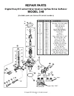
REPAIR PARTS

Digital Noryl® Control Valve Used on Upflow Brine Softener  

MODEL 340

(Available parts are items with circled numbers)

ITEM          PART #              DESCRIPTION

1

137912

Valve body, 13/16” Dist. (upflow)

2 & 3

134829

Spacer and seal kit

4 - 9

137913

Piston assembly kit

22

136486

Injector body

23

134832

Injector nozzle (White #1)

24

134831

Injector throat (White #1)

25

134833

Injector screen

26-28-50

136310

O-ring kit

29

136489

Injector cover

31

136491

Screw, injector cover (2 req’d)

42

136488

BLFC Fitting with O-ring

43

131120

Insert, 1/4” I.D. tube

44

127737

Ferrule,3/8” O.D. tube

46

136494

Retainer, DLFC button

48

130405

2.4 GPM flow control button

52

134848

O-ring, distributor tube

53

134849

O-ring, tank seal

55

127736

Nut, brass, 3/8” comp.

56 & 59

139235

Fastener kit (2 clips, 2 screws)

58

134847

O-ring, adapter coupling (4 req’d)

60

136487

Stem assembly, brine valve

61

135988

2.4 GPM “CS” softener module

Turbine 
Meter Module
(139233)

Bypass Valve 135507

Yoke 134846

Summary of Contents for 340

Page 1: ...basement floor to guard against the possi bility of immersion DISCONNECT POWER AT THE MAIN ELECTRICAL BOX BEFORE INSTALLING OR SERVIC ING THE UNIT DO NOT PLUG IN UNIT OR CHANGE FUSES WHILE STANDING ON WET OR DAMP SUR FACES AND DO NOT TOUCH ANY OTHER METAL SURFACES WHILE PLUGGING IN PRODUCT OR CHANGING FUSES DO IT WITH ONE HAND WHILE KEEPING THE OTHER HAND FREE Check to be sure that your power sour...

Page 2: ...oth 1 2 and 3 4 ID tube the maximum height cannot exceed 8 ft Initially fill the salt brine tank only 3 4 full of salt Do not pack full If any rust stains are apparent use a type of salt available containing iron control agents After installing the unit manually regenerate by following the valve control instructions Make sure that the control head is correctly set for your specific water needs A p...

Page 3: ...able See Diagram A Or contact factory 4 Select location where floor is level If floor is rough and or uneven you can level by placing cabinet or tanks on 3 4 plywood and shim to level as needed 5 Locate the softener in the supply line BEFORE the water heater Temperatures above 100ºF 38ºC will damage the softener and void the warranty INSTALL WATER CONDITIONER IN AN AREA PROTECTED FROM FLOODING RAI...

Page 4: ... kit and dip tester into water sample 4 Compare strip with chart to determine water hardness Retain this number for setting control valve later in the installation process 5 Carefully move unit into approximate installation position 6 Loosen compression nut located on right side of control valve by turning counter clockwise Insert end of 3 8 O D tube making sure tube is pushed in fully Visually ch...

Page 5: ...Position softener near the main water supply line a drain and an electrical outlet Position so that main water supply shut off valve is between the softener and the main water source NOTE Install unit in an area protected from the elements and freezing 10 Close the main water supply shut off valve 11 Open nearest water faucet to relieve pressure and drain plumbing lines 12 On a new installation no...

Page 6: ...ing sure inlet outlet labels face up E Secure all four clips on control valve bypass valve and manifold with screws 15 Diagram shows a 3 valve by pass system Many new homes are plumbed water softener ready in this manner 16 Before installing 3 4 fittings on the inlet and outlet of the manifold wrap the manifold threads three times around with teflon tape Install fittings DO NOT OVER TIGHTEN 17 Sol...

Page 7: ...d pipe with proper 4 air gap NOTE An air gap is required by most local plumbing codes to prevent waste water back flow Check and follow your local codes 22 Install 1 2 I D rigid or non collapsible tubing not included to the overflow hose barb located on the back of the softener brine tank and run to a drain located below the level of the hose barb 23 Plug cord from control valve into a 115V ground...

Page 8: ...gallon bucket of water into the brine tank 28 Measure 1 1 2 oz of chlorine bleach and pour solution directly into the brine tank Required on initial installations only Manually regenerate the softener by pressing the extra cycle button for 8 seconds to run bleach through the softener 29 Pour salt into compartment Fill about 3 4 full initially Do not pack full This is also where iron control salts ...

Page 9: ...o P M indicator B SET GALLONS BETWEEN REGENER ATIONS 1 Depress both the SET UP and SET DOWN buttons at the same time and hold for five seconds A number 800 should appear This is the amount of treated water that can flow through the unit before a regeneration is required This number can be determined from the chart shown in Figure 2 Figure 2 Step 2 Setting For example for a family of three with a w...

Page 10: ...maximum number of days before a regenera tion cycle must occur This should remain in the off setting Press the EXTRA CYCLE button again to return to the time of day setting and exit the programming mode In the event of a power outage the time of day will have to be reset All other functions are maintained in memory and not affected by power interruptions D EXTRA REGENERATION 1 The unit is factory ...

Page 11: ...l be initiated Example 7 1 B METER IMMEDIATE The control will determine that regeneration is required when available volume of softened water drops to or below zero Regeneration to begin immediately Example 7 2 C METER DELAYED This is the factory setting The control will determine that a regeneration is required when the available volume of softened water drops to or below the reserve capacity Reg...

Page 12: ...wash Steps are skipped by setting the display to 0 and regeneration ended by setting the step after the last active step to OFF as shown below Examples Cycle Step 1 backwash 2 min 1 02 0 Cycle Step 2 brine slow rinse 30 min 2 30 0 Cycle Step 3 rapid rinse 2 min 3 02 0 Cycle Step 4 brine tank refill 7 min 4 07 0 Cycle Step 5 not currently used with this valve Must be in off position 5 off Depress t...

Page 13: ...he tank Make sure the resin has not been emptied or dumped Put a trouble light behind resin tank and you should be able to see the resin through the mineral tank approximately 3 4 full Shut off water supply depressurize the unit unscrew the valve head from unit and exchange it Draw a sample of untreated water before it goes through the soft ener and a sample of treated water after the softener Hav...

Page 14: ...se bypass valves Make sure the knobs on the bypass valve are in the service posi tion On a 3 valve bypass position open the inlet and outlet valves and close the bypass valve Salt in bottom of tank has hardened and is not allowing water salt mixture to get to the bottom of salt and consequently over to mineral tank Do not fill salt tank completely 3 4 full Use a stick or broom handle and poke into...

Page 15: ...apac ity and rust stained fixtures Use a type of salt available on the market that contains iron control agents to aid in cleansing the resin bed 3 BRINE TANK CLEAN OUT To prevent serv ice problems the brine tank should be emp tied and cleaned when dirt and other insol ubles accumulate THIS CLEAN OUT SHOULD BE DONE WHEN THE SALT LEVEL IS LOW 4 PERIODICALLY CHECK THE TIME OF DAY SETTING Power outag...

Page 16: ...r Softener MODEL 340 ITEM 1 2 3 4 5 6 7 DESCRIPTION Brine well valve assembly Brine tank less lid w holes Brine tank lid Complete valve upflow brine Mineral tank 13 x 17 Resin package Incl 12 gravel Distributor tube PART NUMBER 137774 138964 137776 137918 137778 138460 138171 ...

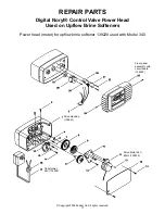
Page 17: ...TS Digital Noryl Control Valve Power Head Used on Upflow Brine Softeners Power head meter for upflow brine softener 139228 used with Model 340 Front panel assembly with circuit board 139230 Drive Housing 139241 Transformer 24V 139238 Drive Motor 24V 60Hz 139232 ...

Page 18: ...1 25 134833 Injector screen 26 28 50 136310 O ring kit 29 136489 Injector cover 31 136491 Screw injector cover 2 req d 42 136488 BLFC Fitting with O ring 43 131120 Insert 1 4 I D tube 44 127737 Ferrule 3 8 O D tube 46 136494 Retainer DLFC button 48 130405 2 4 GPM flow control button 52 134848 O ring distributor tube 53 134849 O ring tank seal 55 127736 Nut brass 3 8 comp 56 59 139235 Fastener kit ...

Page 19: ...19 ...

Page 20: ...20 ...

Reviews: