•
Solu&on step
•
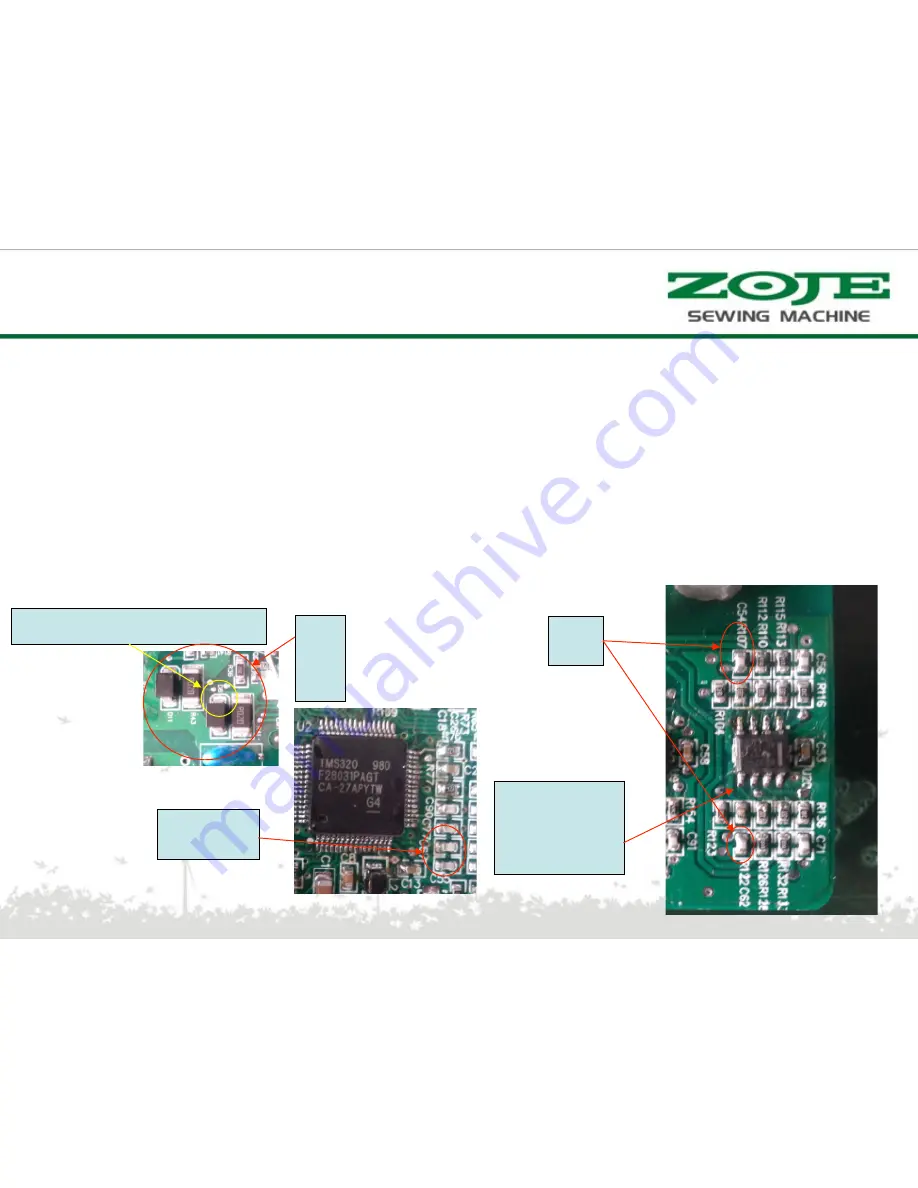
1) detec&on on the main control board impedance between two C55/C67: 13.5K; 80V transformer electric,
measuring voltage is U20 1.46V [1, 7 feet of 4 foot [to] between impedance: 13.5K standby voltage: 1.46V]
•
2) detec&on on the main control board impedance between the ends of 100 C54/C62:?; 80V transformer
electric, measuring voltage 0V
•
3) the main control end of the D8/D11 plate <s, with a mul&meter measuring (block) two diode
resistance: Infinity [nega&ve] does not make a mistake when measuring
Fault detec2on circuit of E14---- current (/CUR_A or /CUR_B signal zero offset
value is too large)
D8
D11
C55/C67
Negative pole-Multimeter black pen
C54
C62
U20
【
OPA2377
pin
】
4
1
5
8
Error solution
Summary of Contents for WR580
Page 1: ...WR580 PRODUCT MANUAL V1 0 ...
Page 2: ...Application Model Code Hardware Structure Error Solution Catalogue ...
Page 5: ...Composition of the product ...
Page 9: ...Model description motor Motor model serial number ...
Page 21: ...Function Aging mode Press to enter the aging mode Then press to start press again to stop ...
Page 24: ...External interface definition power 1 2 3 4 Ground wire Power Socket definition L N ...
Page 28: ...Main board PCBA appearance ...
Page 29: ...Control box theory diagram ...
Page 60: ...谢 谢 ...


