•
Trouble shooting procedure
•
1
)
Adjust the number of parameter 25
•
2
)
Only in the pedal zero point adjustion testing function.it will cause this error.Adjust pedal positioning screw a bit.
•
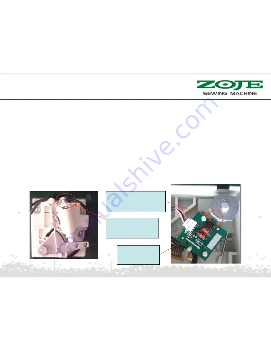
3) Adjust pedal zero point position-procedure
:
•
1
、
install the pedal PCBA.The distance between steel magnet and PCBA should be controlled in
1.5mm~1.8mm,fixing PCBA.
•
2
、
Connect pedal, supply power by 80V isolation transformer, turn the steel magnet, make the output of sensor
voltage (voltage of C2) between 2.77~2.83V.
【
Note: When you adjust pedal, you must us 80V isolation
transformer supply power, the output of voltage is strong current .
】
•
3
、
Check the every positions of cutting to see whether it is normal
。
E15
(
Pedal zero point adjust error
:
zero point adjust over size
(
-1.5degree~1.5
)
Turn screw on pedal
in clockwise,
the angel became bigger,
conversely, smaller
Space between magnetic steel
and sensor of is 1.5mm~1.8mm
C2 ‘s voltage
is 2.77
~
2.83V
Error solution
Summary of Contents for WR580
Page 1: ...WR580 PRODUCT MANUAL V1 0 ...
Page 2: ...Application Model Code Hardware Structure Error Solution Catalogue ...
Page 5: ...Composition of the product ...
Page 9: ...Model description motor Motor model serial number ...
Page 21: ...Function Aging mode Press to enter the aging mode Then press to start press again to stop ...
Page 24: ...External interface definition power 1 2 3 4 Ground wire Power Socket definition L N ...
Page 28: ...Main board PCBA appearance ...
Page 29: ...Control box theory diagram ...
Page 60: ...谢 谢 ...


