•
Solu&on step
•
1
)
Error solution steps
•
To hear whether it is sound of relay when the power is cut.
•
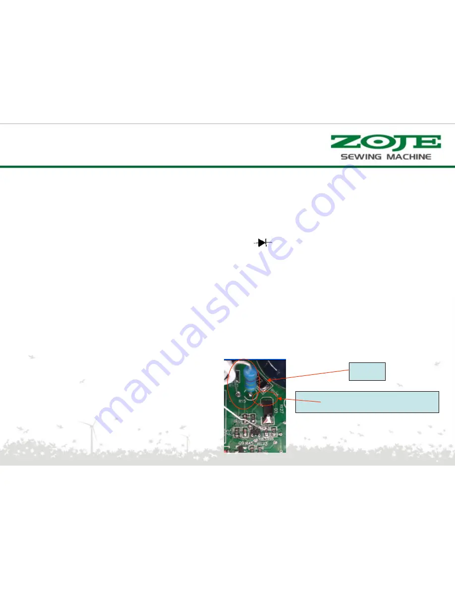
Check impedance of R15:220K, check D3 by channel on multimeter, check the resistance of
diode: 0.48V
•
Access monitoring interface of operation panel to see how much voltage of UDC interface.
•
If the voltage of udc interface is not correct, supply power of 80V by isolation transformer, check
the resistance of R143 which on main board: 100
Ω
; Impedance of C77:around 3.8M; Voltage
of two sides( leg 1 and leg 4[ground] of U9):around 0.56; Impedance of R91: around 1K.
•
Check impedance of C21 on main board: 11.5K;
supply power of 80V by isolation transformer,
standby voltage:around 2.1V; Impedance of R91:around 1K.
•
[
supply power of 80V by isolation transformer] Check impedance of leg 1 and leg 2[ground] of
Q10 which on main board: around 6.6K; standby voltage: around 0.28V; impedance between leg
3 and leg 2[ground]: 10.5K; standby voltage: around 2.1V;
•
[same picture as E16]
•
OFF-Power cut warn(200ms do not detect cut of OZ)
Negative-Black of muitimeter
R15
ERROR SOLUTION
Summary of Contents for WR580
Page 1: ...WR580 PRODUCT MANUAL V1 0 ...
Page 2: ...Application Model Code Hardware Structure Error Solution Catalogue ...
Page 5: ...Composition of the product ...
Page 9: ...Model description motor Motor model serial number ...
Page 21: ...Function Aging mode Press to enter the aging mode Then press to start press again to stop ...
Page 24: ...External interface definition power 1 2 3 4 Ground wire Power Socket definition L N ...
Page 28: ...Main board PCBA appearance ...
Page 29: ...Control box theory diagram ...
Page 60: ...谢 谢 ...


