


lated to Figures
.
19
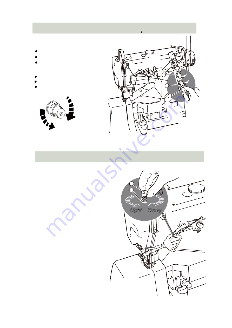
Knob 1: Control the needles thread
Knob 2: Controls the top cover thread
Knob 3: Controls the looper thread
To loosen
1
2
3
The following adjustments are re-
N O '
- . 5 A ] T ^ :
1 9
c d :f g h i
1
c d :f g D E h i
2
c d :f g k h i
3
1 6
(Adjusting the thread tension)
. .
1 7
(Adjusting the presser foot pressure)
. .
to tighten
Figure 19
Loosen adjust nut“1”and turn adjusting
and turn to adjust the
pressure. It should be as
possible to be sufficient to obtain
proper stitch formation.
1
2
Heavy
Light
nut 2
20
“ ”of Figure
presser foot
light as
m n m o T ^ I G p q r “ ” s c t
1
q u “ ” ( ) 5 '
- . 。 v w
2
2 0
y z { | n 5 } ~ , T z
G p ? 。
Figure 20
-12-
Summary of Contents for ZJW663A
Page 5: ...5 1 3 Installing the sewing machine _ X Table Cut Out Drawing Figure 1A D Clutch Motor Z...
Page 20: ...2 1 A Machine bed frame A 4 5 4 7 21 8 18 9 9 10 11 12 1 13 19 6 3 20 2 16 14 15 22 17 20...
Page 54: ...5 6 3 4 2 1 7 8 13 11 12 9 10 14 15 2 13 HR device 54...
Page 60: ...10 9 5 12 11 14 6 13 7 2 3 4 8 1 15 2 16 ESDD Motor structure 60...
Page 64: ...2 18 Integrated Machine Specific Parts 64...


