background image

M S

ERIES

 CCT C

ONFIGURATION

 G

UIDE

24

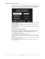
Highlight the Clock Synchronization option and press the 

Change Value 

softkey to display the 

following screen:

Press the 

Change Value 

softkey to scroll through the available values for each parameter.

Press the 

Next Item 

softkey to move to the next parameter in the table.

Press the 

Return

 softkey to save the values entered and return to the main configuration menu.

You can set the values for the following Clock Synchronization options:

Time Zone: 

Selects the time zone in which the M Series CCT will be used. 
Choices include: Azores, Middle Atlantic, S. America Eastern, AST 
Atlantic, EST Eastern, CST Central, MST Mountain, PST Pacific, 
AKST Alaska, HST Hawaiian, Samoa, Dateline, GMT Greenwich, 
CET Central Europe, EET Eastern Europe, MSK Moscow, Arabian, 
Afghanistan, West Asia, Central Asia, Southeast Asia, AWST 
Australian West, Korean, ACST Australian Cent, AEST Australian 
East, Central Pacific, or New Zealand

Dial Location: 

Sets the National Institute of Science and Technology (NIST) dialing 
location to either Hawaii or Colorado. This is the location called by 
the M Series CCT to obtain accurate time information for setting its 
internal clock.

Prefix: 

Affixes up to eight user selectable digits or special characters (+, &, !, 
*, or comma) to the start of the dialing location phone number.

Daylight Savings

When set to “Yes” and the user dials the selected NIST location, the unit will automatically 

adjust the time for Daylight Savings based on the assumption that DST starts on the first 

Sunday in April at 1:59:59 AM (setting the time ahead by one hour) and ends on the last Sunday 

in October at 1:59:59 AM (setting the time back by one hour).

Card Capacity Message Enabled

When set to “Yes” and data recording is enabled with a data card present, the M Series CCT 

will display “CARD LOW” messages when the remaining storage capacity of the card reaches 

30, 15, and 5 minutes. 
To enable this option, the “Report Memory Card Errors” option must be set to “Yes”; otherwise, 

the option is ignored.

Erase Card Prompt at Pwr Off

Sets the M Series CCT unit to allow the user to erase the data card at power-off if the card 

contains only self test, and optionally, synchronized cardioversion data. To enable this option, 

6\VWHP&RQILJXUDWLRQ

3UHY

,WHP

1H[W

,WHP

&KDQJH

9DOXH

(67(DVWHUQ

&RORUDGR

BBBBBBBB

5HWXUQ

7LPH=RQH

'LDO
/RFDWLRQ

'LDO3UHIL[

&ORFN6\QFKURQL]DWLRQ

Summary of Contents for M Series CCT

Page 1: ...CONFIGURATION GUIDE 9650 0204 01 Rev A October 2006...

Page 2: ...t ZOLL Medical Corporation to determine if additional product information updates are available ZOLL M Series and stat padz are registered trademarks and PD and XL are trademarks of ZOLL Medical Corpo...

Page 3: ...ISPLAY ECG IN SEMI AUTO MODE 12 STORE TO CARD IN AUTO MONITOR MODE AED MODELS 13 AUTO CHARGE IN ADVISORY MODE 13 RECORD TO CARD IN ADVISORY MODE 13 ENABLE VOICE IN ADVISORY MODE 13 DISPLAY HEART RATE...

Page 4: ...ME AED SEMI AUTOMATIC MODE 22 BATTERY TYPE USED 22 ALARM LIMITS AT POWER UP 23 ALARMS ACTIVE AT POWER UP 23 LOW BATTERY TONE 23 CLOCK SYNCHRONIZATION 23 DAYLIGHT SAVINGS 24 CARD CAPACITY MESSAGE ENABL...

Page 5: ...he rightmost and leftmost softkeys Turn the selector switch to MONITOR or ON while holding the buttons depressed for approximately four 4 seconds After four 4 seconds the following screen will appear...

Page 6: ...ents is printed after changing languages the Code Marker events will not match Press the Enter softkey to select the highlighted language and move to the Main Configuration menu All subsequent configu...

Page 7: ...ill cause the unit to print the current unit configuration settings Restore Defaults Pressing the Restore Defaults softkey causes the unit to reconfigure to its default settings See the Configuration...

Page 8: ...configura tion card has been read and loaded the Card Read and Press Change Config to View mes sages display see below If there is an error reading the memory card one of the following error messages...

Page 9: ...e Config softkey causes the unit to display the first configuration option menu There are three user configurable features contained within each option menu Refer to the Configuration Option Tables on...

Page 10: ...M SERIES CCT CONFIGURATION GUIDE 6 This page has intentionally been left blank...

Page 11: ...reen when other previously displayed option menus are available Press the Prev Item softkey until the previous menu is displayed Notch Filter Sets the ECG Notch Filter frequency for proper AC mains in...

Page 12: ...t will print When set to None pressing and holding the RECORDER button will cause a one or three lead DIAG BANDWIDTH ECG strip to be printed Auto Self Test Timeout Period Allows the user to set the ti...

Page 13: ...the entire Marker List Press the Enter Marker softkey to replace the highlighted item in the Defib markers column with the highlighted clinical action in the Marker List Pressing the Prev Item or Next...

Page 14: ...tem it is recommended that you set up the device identifier Pressing the Change Value softkey causes the following screen to display Pressing the Prev Letter softkey moves the highlight left to the pr...

Page 15: ...digit to be entered Pressing the Enter softkey selects the values that have been entered and returns to main configuration menu Configuration Mode Passcode Sets an eight digit Configuration Passcode E...

Page 16: ...s described above only when it is in AED semi auto mode If the unit is changed to Manual mode when set to Only in Semi auto any automatic analysis reanalysis sequencing terminates If the Analyze butto...

Page 17: ...y Lead on Power Up Allows the user to select any one of the following Leads to be displayed on power up Paddles Pads I II or III When the unit powers up in semi automatic mode the option is ignored Th...

Page 18: ...ure Print 3 Leads When Leads Sel When enabled the strip chart recorder will automatically print three 3 simultaneous leads of the patient ECG when Leads are selected and a five 5 lead or 12 lead ECG c...

Page 19: ...E Site and Location on page 21 It is also recommended that you set up the M Series device identifier see Device Identifier on page 10 Updating Fax Communication Information To transmit data to a fax m...

Page 20: ...to select digit 2 Press Inc Letter or Dec Letter softkey to change value of digit Repeat steps 1 and 2 until entire phone number has been entered 3 Press Enter softkey to move cursor to Fax or Data f...

Page 21: ...ion When set to Yes any faxed 12 lead report will contain two pages The second page of the report will contain the computed measurements matrix 12 Lead Fax Format When set to 4x3 Standard the 12 lead...

Page 22: ...ng defaults to 0 05 40 Hz 4x3 Refer to the 12 Lead ECG Monitoring Operator s Guide insert part number 9650 0215 01 for details on each setting Lead Group Default When set to Standard the 12 Lead Group...

Page 23: ...ys in place of the ECG waveform Yes is the default setting Note When using 12 Lead or Pacer mode the M Series CCT unit functions as if this configuration were set to Yes When set to No and ECG leads d...

Page 24: ...unit automatically increments the defibrillation energy to the levels specified in Energy Level Shock 1 2 3 after each of the first two shocks and displays the message ENERGY INCREMENTED when both of...

Page 25: ...d location values and return to main configuration menu 12 Lead Secs Per Lead Sets the number of seconds of ECG data printed for each lead on the 12 lead 4x3 strip This setting only affects 12 lead re...

Page 26: ...INGS If an XL battery is installed in an M Series CCT the user must ensure that the BATTERY TYPE USED is set to XL Battery Otherwise the M Series CCT may abnormally terminate battery charging prior to...

Page 27: ...ey moves the highlight to the next field in the table Pressing the Return softkey selects the values that have been entered and returns to the main configuration menu Alarms Active at Power Up When se...

Page 28: ...lled by the M Series CCT to obtain accurate time information for setting its internal clock Prefix Affixes up to eight user selectable digits or special characters or comma to the start of the dialing...

Page 29: ...ed a defibrillation other than a self test since power up Note The M Series CCT unit can be configured NOT to display the Remove Card prompt if the card contains only synchronized cardioversion data S...

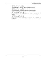
Page 30: ...s the user to set the parameter displayed on the second and third traces respectively on the M Series CCT monitor when the unit is powered up Highlight the Power Up Trace Selection option and press th...

Page 31: ...Power Up Sets the label assigned to the second IBP channel when the unit is powered up IBP1 Range at Power Up Sets the default display scale in mmHg for the waveform amplitude of the first IBP channel...

Page 32: ...M SERIES CCT CONFIGURATION GUIDE 28 This page has intentionally been left blank...

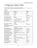
Page 33: ...in Pace Mode Yes No Yes Code Markers Defib Code Markers Monitor Code Markers Pace Code Markers Config Review Config Review Device Identifier 0 through 9 A through Z blank and _ inclusive for each dig...

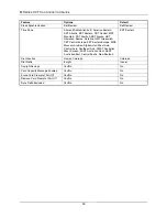
Page 34: ...e EET Eastern Europe MSK Moscow Arabian Afghanistan West Asia Central Asia Southeast Asia AWST Australian West Korean ACST Australian Cent AEST Australian East Central Pacific New Zealand EST Eastern...

Page 35: ...75 100 120 150 200 J Manual DSW 360 J Manual Biphasic 200 J AED DSW 360 J AED Biphasic 200 J Auto Analyze 3 Times Yes No Only in Semi Auto Manual No AED Only in Semi Auto NO SHOCK ADVISED Prompt NO SH...

Page 36: ...No Set Lead Groups Set Review Set Review Custom Group 1 3 leads Custom Group 2 3 leads For each lead I II III aVR aVL aVF V1 V2 V3 V4 V5 V6 Custom Group 1 II III aVF Custom Group 2 II III V1 12 Lead...

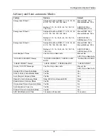
Page 37: ...er NIBP Meas on HR Alarm Yes No No NIBP First Inflate Pressure Default Set Review Set Review Adult Initial Cuff Inflation CCT models in mmHg 120 140 160 180 200 220 240 260 in kPa 16 0 18 7 21 3 24 0...

Page 38: ...Label at Power Up P1 ART PA CVP ICP P1 IBP2 Label at Power Up P2 ART PA CVP ICP P2 IBP1 Range at Power Up in mmHg 0 300 0 180 0 120 0 60 0 30 in kPa 0 40 0 24 0 16 0 8 0 4 0 300 mmHg IBP2 Range at Pow...

Reviews: