background image

Propaq

®

 MD Operator’s Guide

9650-0806-01 Rev. D

Summary of Contents for Propaq MD

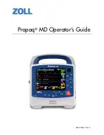
Page 1: ...Propaq MD Operator s Guide 9650 0806 01 Rev D...

Page 2: ...elp Rectilinear Biphasic RescueNet See Thru CPR stat padz SurePower and ZOLL are trademarks or registered trademarks of ZOLL Medical Corporation in the United States and or other countries All other t...

Page 3: ...8 Semiautomatic Operation AED 1 8 ECG Monitoring 1 9 CPR Monitoring 1 9 External Transcutaneous Pacing 1 9 Non Invasive Blood Pressure Monitoring 1 9 Temperature Monitoring 1 9 SpO2 Monitoring 1 9 Res...

Page 4: ...s 1 24 Notification of Adverse Events 1 25 Software License 1 25 Service 1 26 The ZOLL Serial Number 1 27 Chapter 2 Product Overview Defibrillator Controls and Indicators 2 1 The Front Panel 2 2 Displ...

Page 5: ...Visual Alarm Indicators 5 1 Audible Alarm Indicators 5 2 Alarm Indicator Self Test 5 2 Patient Alarm Display 5 3 Life Threatening Rhythm Alarms 5 4 Equipment Alert Display 5 4 Responding to Active Ala...

Page 6: ...essure NIBP How does NIBP Work 8 2 The NIBP Numeric Display 8 3 NIBP Setup and Use 8 3 Selecting the NIBP Cuff 8 4 Connecting the NIBP Cuff 8 5 Applying the Cuff to the Patient 8 7 Ensuring Correct Cu...

Page 7: ...the SpO2 Averaging Time 10 11 Selecting the SpO2 Sensitivity 10 11 Selecting the Heart Rate Pulse Rate HR PR Tone 10 11 SpO2 System Messages 10 11 Functional Testers and Patient Simulators 10 13 Chap...

Page 8: ...Switching to Manual Mode Operation 13 10 Chapter 14 12 Lead ECG Interpretive Analysis Entering Patient Information 14 2 Entering the Patient Name and ID 14 3 Entering Patient Age and Gender 14 4 12 L...

Page 9: ...0 Synchronized Cardioversion 15 11 Synchronized Cardioversion Procedure 15 12 Determine the Patient s Condition and Provide Care Following Local Medical Protocols 15 12 Prepare Patient 15 12 Turn On U...

Page 10: ...ing in Fixed Mode 18 6 1 Turn On Unit 18 6 2 Apply ECG Electrodes Hands Free Therapy Electrodes 18 6 3 Press Pacer button 18 7 4 Set Mode 18 7 5 Set Pacer Rate 18 7 6 Turn On Pacer 18 7 7 Set Pacer Ou...

Page 11: ...ernet Connection 22 10 WiFi Access Point Profiles 22 13 Setting up Cellular Communications 22 19 Setting up an Ethernet Connection 22 23 Configuring Report Transmissions 22 24 Sending a 12 lead report...

Page 12: ...phasic Waveform A 25 Randomized Multicenter Clinical Trial for Defibrillation of Ventricular Fibrillation VF and Ventricular Tachycardia VT A 25 Randomized Multi Center Clinical trial for Cardioversio...

Page 13: ...of options in Fig 1 1 All features are included in this manual but only purchased features will be available on your unit The product is designed for use in hospital EMS and rugged military environmen...

Page 14: ...ECG sensing circuitry Pacing supports both demand and fixed noninvasive pacing for adult patients and adolescent child and infant pediatric patients The Propaq MD has a patient data review and collect...

Page 15: ...mation updates are available All users should carefully review each manual update to understand its significance and then file it in its appropriate section within this manual for subsequent reference...

Page 16: ...iption Dangerous voltage Attention consult accompanying documents Fragile handle with care Keep dry This end up Temperature limitation Conformit Europ enne Complies with medical device directive 93 42...

Page 17: ...liary power adapter operation Caution high voltage Earth ground Negative input terminal Positive input terminal Power On Off Protective earth ground Contains lithium Recycle or dispose of properly Kee...

Page 18: ...on site intended for waste electrical and electronic equipment WEEE Do not dispose of in unsorted trash Date of manufacture Use by Latex free Do not reuse Do not fold Not sterile Manufacturer Authoriz...

Page 19: ...also intended for use by or on the order of physicians at the scene of an emergency or in a hospital emergency room intensive care unit cardiac care unit or other similar areas of a hospital The usag...

Page 20: ...l must decide when synchronized cardioversion is appropriate The patient population will range from newborn neonate to adult Semiautomatic Operation AED Propaq MD products are designed for use by emer...

Page 21: ...tion from standstill or bradycardia of any etiology As a standby when standstill or bradycardia might be expected Suppression of tachycardia Pediatric pacing Non Invasive Blood Pressure Monitoring The...

Page 22: ...ded for use to display and make continuous invasive pressure measurements from any compatible pressure transducer The primary intended uses are arterial blood pressure central venous pressure and intr...

Page 23: ...greater than 100 ppm The pacing output pulse is delivered to the heart via ZOLL hands free defibrillation pacing electrodes placed on the patient s back and the precordium Proper operation of the dev...

Page 24: ...power adapter to automatically begin charging the installed battery pack The front panel battery indicator operates as follows Note Upon power up it takes approximately 45 seconds for the LEDs on the...

Page 25: ...installed A low battery is installed A battery fault has occurred There is no battery installed while connected to auxiliary power One or more patient monitoring parameters have failed self test NIBP...

Page 26: ...must be determined before attempting defibrillation These operating instructions describe the functions and proper operation of the Propaq MD products They are not a substitute for a formal patient c...

Page 27: ...f uncertain about the accuracy of any measurement first check the patient s vital signs by alternate means and then make sure the monitor is functioning correctly ECG Monitoring Implanted pacemakers m...

Page 28: ...remain in the SYNC mode after each synchronized cardioversion Synchronized cardioversion can be performed in the paddle monitoring mode However it is possible that artifact can be produced by the movi...

Page 29: ...ssation of pacing particularly at rapid rates can cause ventricular standstill and should be avoided Noninvasive temporary pacing can cause discomfort of varying intensity which occasionally can be se...

Page 30: ...PR The CPR monitoring function is not intended for use on patients under 8 years of age Place the patient on a firm surface before performing CPR The patient must be motionless during CPR for accurate...

Page 31: ...pressure readings The correct size cuff is essential for accurate blood pressure readings Blood pressure hoses must be free of obstructions and crimps If the patient s cuff is not at heart level an e...

Page 32: ...y The device should not be used as an apnea monitor Ferromagnetic Equipment Biomedical equipment and accessories such as ECG electrodes cables and oximeter probes contain ferromagnetic materials Ferro...

Page 33: ...defibrillator only when defibrillation electrodes or paddles are properly applied to the patient To avoid risk of electrical shock do not touch the gelled area of the hands free therapy electrodes du...

Page 34: ...lation energy level settings should be based on site specific clinical protocols To ensure patient safety do not place the monitor in any position that might cause it to fall on the patient To ensure...

Page 35: ...led or splashed liquids thoroughly dry all exposed surfaces of this device prior to operation or connections to auxiliary power If liquids enter the device connectors remove all liquid from the connec...

Page 36: ...ered a New Patient and all of the patient specific parameters alarm limits defibrillator energy etc will be reset to their default values FDA Tracking Requirements U S Federal Law 21 CFR 821 requires...

Page 37: ...yment of the software license fee which is part of the price paid for this product ZOLL Medical Corporation grants the Purchaser a non exclusive license without right to sublicense to use the system s...

Page 38: ...ilable and applicable less any confidential patient information Returning a unit for service Before sending a unit to the ZOLL Technical Service Department for repair obtain a service request SR numbe...

Page 39: ...of manufacture code gives the month in which the product was manufactured The month appears in the form of a single alphanumeric character A for January B for February C for March and so on through L...

Page 40: ...CHAPTER 1 GENERAL INFORMATION 1 28 www zoll com 9650 0806 01 Rev D...

Page 41: ...9650 0806 01 Rev D Propaq MD Operator s Guide 2 1 Chapter 2 Product Overview Defibrillator Controls and Indicators 2 1 5 7 8 3 5 5 6 9 4...

Page 42: ...ry controls 3 Speaker Emits R wave detection beeps and alarm tones 4 Paper Compartment Holds the paper for the printer 5 Patient connectors For details refer to Patient Cables and Connectors on page 2...

Page 43: ...sh on and off when the unit is powered up and are used to indicate a patient alert equipment alert and data transfer Pacer button Displays pacer settings window to start stop pacing activity or change...

Page 44: ...gate through a vertical list or in a counterclockwise direction if the cursor is being used to navigate around the full screen The up clockwise and down counterclockwise arrows may also be used to mod...

Page 45: ...yout of parameter values waveforms system data and quick access key labels Figure 2 2 Propaq MD Display Screen Color coding To differentiate information for various parameters the unit displays each t...

Page 46: ...tes after exiting the defibrillation mode Icon Status Indication Action Auxiliary power adapter is connected The unit is being powered by the auxiliary power adapter No battery detected Either there i...

Page 47: ...lude sets of connectors for patient cables Note The SPO2 NIBP CO2 Temperature and IBP functions are optional If your unit does not include these options it does not have the applicable connectors Figu...

Page 48: ...onnector in with the arrows aligned The connector will click when it locks into place Connector Description ECG For connecting 3 or 5 lead ECG cable 12 lead monitoring is optional SpO2 For connecting...

Page 49: ...pull out the MFC connector OneStep Cable optional The OneStep cable is used with OneStep electrodes for ECG monitoring and for use with Real CPR Help Figure 2 6 OneStep Cable When connecting a OneSte...

Page 50: ...nd synchronized cardioversion Caution You cannot use paddles for external transcutaneous pacing Attaching the MFC cable Attach the MFC from the Propaq MD unit to the connector at the base of the APEX...

Page 51: ...electrode to the OneStep cable push the two connectors together until the latch clicks as shown When disconnecting the OneStep electrode and OneStep cable press down the latch with your thumb as shown...

Page 52: ...and unplug the OneStep cable Refer to Chapter 15 Manual Defibrillation before using paddles for defibrillation The paddles include controls for selecting defibrillation energy charging and delivering...

Page 53: ...ed as backup power to operate the Propaq MD unit When it is connected to the unit it powers the unit and charges the battery that is installed inside it When the power cord is plugged in and the auxil...

Page 54: ...Auxiliary Power Adapter Navigating the Display Screen You can access the Propaq MD functions using the quick access keys that are located on the left side of the display screen and the navigation key...

Page 55: ...setting toggles through high contrast display white background color display black background and night vision goggle NVG friendly display Treatment Displays the current clinical treatment options Al...

Page 56: ...ccompany 12 lead data patient name age gender and ID Row Up Allows you to move to the previous row when entering patient information Row Down Allows you to move to the next row when entering patient i...

Page 57: ...rightness The monitor can display in two different brightness modes high contrast with white background for optimal display in bright sunlight color with black background numerics and waveforms are ea...

Page 58: ...han when choosing a lower brightness setting such as 30 To select the brightness setting go to the Setup Display Volume Display Brightness menu to adjust the display percentage Replacing a Battery Pac...

Page 59: ...inistered to the patient to a Treatment Summary Report You can do this by selecting Print on Treatment Snapshot from Setup Supervisor Printer The following is a list of preconfigured treatment buttons...

Page 60: ...CHAPTER 2 PRODUCT OVERVIEW 2 20 www zoll com 9650 0806 01 Rev D...

Page 61: ...unit also allows you to set alarm limits for each monitoring function Should a patient s vital signs measurements go outside of these limits the Propaq MD issues an audible alarm tone and displays vis...

Page 62: ...unction Temperature The Temperature Temp meter can display temperature measurements from up to two temperature probes The Propaq MD unit provides two separate temperature monitoring channels and if bo...

Page 63: ...lobin saturation SpMet SpO2 monitoring determines the ratio of oxygenated hemoglobin to total hemoglobin in arterial blood and displays this ratio as percent SpO2 in a labeled SpO2 numeric display If...

Page 64: ...the Home Display button when viewing the Waveform Display window and the unit displays the Trends Status window The Trends Status window reports the patient s vital sign measurements which the Propaq...

Page 65: ...56 Adult 00 17 43 I II III 12 CO2 Analyze IBP 1 cm mV II HR bpm 80 NIBP mmHg 121 79 96 EtCO2 mmHg 12 BR 38 SpO2 97 T1 F 98 6 NIBP Trends Time HR PR bpm NIBP mmHg SpO2 RR BR br min 12 20 21 81 122 60...

Page 66: ...no waveform trace appears on this screen Press the Home Display button to redisplay the Primary Display window Note When the Propaq MD unit is displaying the Defibrillation or Pacing Control panels t...

Page 67: ...splay four ECG traces on startup when no other monitoring devices are attached The Propaq MD unit can also cascade a trace onto the adjoining trace area to double the duration of the trace display On...

Page 68: ...wo more waveform traces into the window A third trace is inserted for ECG lead aVR and fourth trace for EtCO2 a capnogram Notice that when the third trace is inserted the numeric displays move to the...

Page 69: ...2012 12 34 56 Adult 00 17 43 I II III 12 CO2 Analyze IBP 1 cm mV II HR bpm 80 121 79 96 NIBP mmHg 38 12 BR CO2 mmHg SpO2 97 T1 F 98 6 Pads III aVL aVF V Insert Source II I Cascade aVR 06 06 2012 12 3...

Page 70: ...CO2 1 cm mV aVR 1 cm mV II HR bpm 80 NIBP mmHg 121 79 96 EtCO2 mmHg 12 BR 38 SpO2 97 T1 F 98 6 Pads I II III aVR aVL aVF V SpO2 Source P1 P2 P3 Insert Cascade Remove Resp CO2 Analyze IBP 06 06 2012 1...

Page 71: ...on You press the Snapshot button on the front panel A patient alarm occurs and the Trend on Alarm option is on The Propaq MD unit can store at least 24 hours of trend information when logged at a 1 mi...

Page 72: ...he navigation keys to highlight the Navigate Here to Scroll Through Trends bar then press Select 2 Press the Up Down buttons to scroll through the trend information 3 To print all trends for the curre...

Page 73: ...then selecting Supervisor Log Waveform Recording In this menu the following settings can be customized Record Displayed Waveforms Record only the top waveform that is displayed or record all waveforms...

Page 74: ...CHAPTER 4 TRENDS 4 4 www zoll com 9650 0806 01 Rev D...

Page 75: ...are not user configurable Patient alarms are always classified as high priority alarms Technical alerts are classified as medium or low priority alarms Alarm conditions from patient alarms and techni...

Page 76: ...self test of the audio and visual alarm indicators upon power up To ensure that the alarms and alerts are functioning properly verify that two alarm tones are heard and the green yellow and red LEDs...

Page 77: ...ge and changes the display characteristics of the monitoring function s numeric display the alarming parameter appears in red against a white background In the following example the EtCO2 measurement...

Page 78: ...Alert Display When a problem with the Propaq MD unit or an attached sensor triggers an alert in addition to sounding an equipment alert the Propaq MD unit displays an alert message yellow background...

Page 79: ...alarm before the alarm silence period has expired press the Alarm Silence Reset button Warning Do not silence the audible alarm if patient safety may be compromised Suspending Alarms When caring for a...

Page 80: ...ion the window displays an alarm suspension timer at the top of the display next to the message area 06 06 2012 12 34 56 Adult 00 17 43 I II III 12 CO2 Analyze IBP 1 cm mV II HR bpm 80 121 79 96 NIBP...

Page 81: ...ess the Setup quick access key and select Supervisor Using the navigation keys select the four digits in the Supervisor passcode Press SAVE when you are finished Once you have entered your supervisor...

Page 82: ...ts by performing the following actions 1 Press 2 Press the Alarm quick access key 3 Press the Stat Set quick access key The Propaq MD unit sets all parameters to a new value based on the current value...

Page 83: ...r limit 0 SpMet Entire range Limit Numeric 2 Upper limit 15 Limit Numeric 2 Lower limit 0 EtCO2 mmHg Entire range Limit Numeric 10 Limit Numeric 5 mmHg unless the numeric falls below the lower alarm l...

Page 84: ...CHAPTER 5 ALARMS 5 10 www zoll com 9650 0806 01 Rev D...

Page 85: ...air or wet sweaty skin may interfere with electrode adhesion Remove the hair and or moisture from the area where the electrode is to be attached Use only electrodes that are well within the expiration...

Page 86: ...CG monitoring Good contact between the electrode and skin minimizes motion artifact and signal interference The following procedure describes how to monitor a patient s ECG using 3 and 5 Lead ECG cabl...

Page 87: ...odes are placed to allow defibrillation if necessary 3 Lead Electrode Placement Depending upon local usage the ECG leads are marked either RA LA and LL or R L and F The following table shows the marki...

Page 88: ...e directly below clavicle LL Red Electrode F Green Electrode Place between 6th and 7th intercostal space on patient s left mid clavicular line RL Green Electrode N Black Electrode Place between 6th an...

Page 89: ...de Placement Connecting the ECG Cable To the Propaq MD Unit The Propaq MD unit accepts Welch Allyn Propaq ECG cables as well as ZOLL Propaq MD ECG cables Connect the ECG cable to the ECG connector on...

Page 90: ...aveform trace One way is to press the ECG lead selection quick access key to display the available ECG waveform sources The available waveform sources are determined by the type of ECG cable connected...

Page 91: ...that is not currently available the unit displays the message LEAD FAULT For more information on how to configure the display of waveforms on the Propaq MD unit see Chapter 3 Monitoring Overview 06 06...

Page 92: ...t the trace size that appears to the right of the electrode label The default trace size is 1cm mV You can select a larger 2 0 4 0 cm mV or smaller 0 125 0 25 0 50 cm mV trace size You can also specif...

Page 93: ...pulses from the waveform display or print the vertical dashed line pacer markers You can turn the Pacer Indicator ON OFF from the Setup ECG menu There are situations where ECG artifact could simulate...

Page 94: ...CHAPTER 6 MONITORING ECG 6 10 www zoll com 9650 0806 01 Rev D...

Page 95: ...ate HR The Propaq MD unit displays Respiration Resp and Heart Rate HR meters The Respiration and Heart Rate meters display values that the Propaq MD unit derives from measurements taken by other Propa...

Page 96: ...Impedance pneumography detects respiratory effort through changes in chest volume However No Breath episodes with continued respiratory effort may go undetected Always monitor and set alarms for SpO2...

Page 97: ...ied respiration rate alarm limits To enable or disable Resp alarms and set Upper and Lower alarm limits you can either do so through the Alarms quick access key or the Resp Parameter Control Panel To...

Page 98: ...Resp Parameter Control Panel allows you to set the following parameters RR BR Alarm enable disable the Resp alarm and set high low alarm limits No Breath Alarm sets the duration of the No Breath alarm...

Page 99: ...t Rate Meter The Heart Rate meter displays the heart rate that it derives from the ECG monitoring function by default or from a monitoring function that you specify If the ECG or user specified monito...

Page 100: ...you want to change Upper Limit Enable Lower Limit Enable Upper Limit Lower Limit When you are finished changing values on the alarm menu navigate to the Backarrow key to confirm your choices and exit...

Page 101: ...shots and Continuous Waveform printouts The following example shows an Asystole alarm event To enable or disable LTA alarms and set Extreme Brady Tachy alarm limits you can either do so through the Al...

Page 102: ...Extreme Tachycardia LTA alarm detection to be enabled The Extreme Bradycardia and Extreme Tachycardia LTA alarms will not activate until 20 seconds after the alarm limit threshold is crossed The follo...

Page 103: ...Control Panel Selecting the HR PR Alarm prompt displays the HR PR Alarm Settings menu on which you can enable disable Heart Rate alarms and set alarm limits RESP System Message When monitoring Respira...

Page 104: ...Chapter 7 Monitoring Respiration Resp and Heart Rate HR 7 10 www zoll com 9650 0806 01 Rev D...

Page 105: ...q MD unit to take an NIBP measurement as the cuff is inflating which saves time the measurement takes about 15 seconds and improves patient comfort The Smartcuf monitoring software enables the Propaq...

Page 106: ...ulates the blood pressure measurements accordingly The pressure measurement proceeds as follows 1 The cuff inflates to a preconfigured pressure determined by patient type above the patient s systolic...

Page 107: ...s chapter Read each section carefully before you perform NIBP measurements 1 Select the correct size cuff 2 Apply the cuff to the patient 3 Connect the inflation hose to the Propaq MD unit and to the...

Page 108: ...the patient s actual blood pressure Using a cuff that is too large results in measurements lower than the patient s actual blood pressure The Propaq MD unit uses the same definitions of Neonates Pedi...

Page 109: ...ube adaptor and hose You can also use a single lumen one tube hose and adaptor with the Propaq MD unit but the unit will only measure blood pressure on cuff deflation To connect the NIBP cuff to the P...

Page 110: ...CHAPTER 8 MONITORING NON INVASIVE BLOOD PRESSURE NIBP 8 6 www zoll com 9650 0806 01 Rev D Attach a single lumen hose as follows Figure 8 2 Attaching Single Lumen Hose to the Propaq MD Unit...

Page 111: ...re placing it on the patient 3 Place the cuff 2 to 5 cm above the elbow crease or 5 to 10 cm 1 9 to 3 9 in above the knee crease Warning Do not place the NIBP cuff on the same arm or leg as an SpO2 se...

Page 112: ...nd to the right possible cuff placements for neonates Figure 8 3 Applying Cuff to the Patient Ensuring Correct Cuff Inflation Settings Before taking an NIBP measurement for a new patient ensure that t...

Page 113: ...ts is to ensure that the necessary alarms are enabled or disabled that alarm limits are appropriate and that the NIBP settings are correct Enabling Disabling NIBP Alarms and Setting Alarm Limits When...

Page 114: ...hese limits Setting Upper and Lower Diastolic Alarm Limits Initially the NIBP Diastolic Alarm Settings menu specifies that the NIBP diastolic pressure alarms are enabled ON or disabled OFF and display...

Page 115: ...you can set these limits Using the NIBP Parameter Control Panel Use the navigation keys to highlight and select the NIBP numeric display to display the NIBP Parameter Control Panel Figure 8 4 NIBP Pa...

Page 116: ...and manually initiate an NIBP reading at any time while in Automatic Mode Manually initiated NIBP readings will not affect the timing of subsequent NIBP readings in Automatic Mode Specify the Automati...

Page 117: ...o perform as many NIBP measurements as possible over a 5 minute period Select Stop TurboCuf to immediately stop STAT measurements WARNING Repeated use of STAT measurements on the same patient over a s...

Page 118: ...patient mode as appropriate If the detection is in error dismiss the alert and reattempt the NIBP measurement AIR LEAK A major air leak is preventing cuff inflation Check hose and cuff connections rep...

Page 119: ...OUT OF RANGE The NIBP module is outside of its operating temperature range Move unit to proper operating temperature and reattempt the NIBP measurement WEAK PULSE The patient s pulse is too weak to ob...

Page 120: ...CHAPTER 8 MONITORING NON INVASIVE BLOOD PRESSURE NIBP 8 16 www zoll com 9650 0806 01 Rev D...

Page 121: ...ed for CO2 measurements on intubated and non intubated infant pediatric and adult patients The Microstream CO2 sensor generates infrared light and beams it through the sampled breathing gases and dete...

Page 122: ...omponents and check connections for leaks according to standard clinical procedures Always ensure the integrity of the patient breathing circuit after insertion of the airway adapter by verifying a pr...

Page 123: ...orporation does not guarantee the use of non authorized accessories Accessory Type Part Number FilterLine Set Adult Pediatric box of 25 Intubated sampling line and airway adapter for short term monito...

Page 124: ...connect the FilterLine or Smart CapnoLine 1 Slide open the Propaq MD unit s CO2 inlet port cover 2 Put the fitting at the end of the sidestream tubing over the CO2 inlet port connector 3 Turn the fit...

Page 125: ...to the manufacturers instructions The gas scavenging system should comply with ISO 8835 3 1997 E Note In order to avoid moisture buildup and sampling line occlusion during nebulization or suction for...

Page 126: ...ed breath WARNING The disposable Smart CapnoLine nasal and nasal oral cannula sets are intended for single patient use Do NOT reuse or sterilize any part of this product as the monitor may be damaged...

Page 127: ...d after a delay of approximately 1 minute the patient s Respiration Rate in Breaths Minute identified as BR Check that connections have been made correctly by verifying the display a proper capnogram...

Page 128: ...le CO2 alarms and set upper and lower alarm limits through the Alarms quick access key or the CO2 Parameter Control Panel To configure CO2 alarms through the Alarms quick access key 1 Press the More q...

Page 129: ...MD unit in high altitude environments it is advisable to adjust EtCO2 alarm settings accordingly Setting Upper FiCO2 Limits Initially the FiCO2 Alarm menu specifies that the FiCO2 alarms are enabled O...

Page 130: ...eric display to display the CO2 Parameter Control Panel Figure 9 2 CO2 Parameter Control Menu On the CO2 Parameter Control Panel you can select a CO2 alarm EtCO2 Breath Rate or FiCO2 On the selected a...

Page 131: ...terLine is correctly attached replace the FilterLine AUTO ZERO The Propaq MD unit displays AUTO ZERO when the CO2 module performs periodic self maintenance During self maintenance the CO2 module perfo...

Page 132: ...29 and their foreign equivalents Additional patent applications pending NO IMPLIED LICENSE Possession or purchase of this device does not convey any express or implied license to the device with unaut...

Page 133: ...through the body s extremities The transmitted light is then received by a photodetector which converts it to an electronic signal The signal is then sent to the Propaq MD unit for processing Oxygen s...

Page 134: ...anglement or strangulation Inaccurate measurements may be caused by venous pulsations The pulse oximeter can be used during defibrillation but the readings may be inaccurate for a short time Pulse rat...

Page 135: ...itored with a pressure cuff or with restricted blood flow A poorly applied sensor might give incorrect saturation readings A weak pulse signal on the display might indicate a poorly applied sensor or...

Page 136: ...s a list of ZOLL approved reusable and single use SpO2 sensors for adult pediatric and neonate patients Before applying the sensor always familiarize yourself with the Directions for Use that the manu...

Page 137: ...le of the sensor is centered on the tip of the digit Wrap adhesive flaps on non cable end around the digit Note that the cable must be positioned on the top of the hand 3 Fold cable end over top of di...

Page 138: ...0 1 Plug the Sensor Connectors Together 5 Lower the clear plastic cover over the connection to secure it Figure 10 2 Lower Plastic Cover Over Cable Connection 6 See Connecting the SpO2 Sensor on page...

Page 139: ...may extend over and past the finger stop 3 Check the sensor position to ensure that the top and bottom halves of the sensor are parallel To ensure accurate data you must have complete coverage of the...

Page 140: ...Figure 10 3 Connecting the SpO2 Sensor to the Propaq MD Unit Displaying SpO2 SpCO and SpMet Measurements When the connection is made between the SpO2 sensor and the unit the message INITIALIZING appea...

Page 141: ...selection SpO2 SpCO SpMet 5 On the selected Alarm Settings menu use the navigation keys to select the fields that you want to change The fields are Upper Limit Enable Lower Limit Enable Upper Limit L...

Page 142: ...the patient Figure 10 4 SpO2 Parameter Control Menu Selecting the SpCO and SpMet Monitoring If SpCO and SpMet are installed the Propaq MD unit allows you enable or disable SpCO and SpMet monitoring P...

Page 143: ...der very low perfusion conditions Such conditions may include severe hypotension or shock With the High sensitivity setting however SpO2 results are more easily contaminated by artifact To ensure accu...

Page 144: ...he scope of known bench top testers including known devices which claim to measure sensor LED wavelength SpO2 measurement accuracy can only be evaluated in vivo by comparing pulse oximeter readings wi...

Page 145: ...5uV V mmHg sensitivity Each channel requires its own connector cabling and pressure transducer Invasive Pressure Transducers The Propaq MD unit is compatible with many types of invasive pressure tran...

Page 146: ...sensors may result in inaccurate IBP measurements IBP Setup To take safe and accurate IBP measurements using the Propaq MD you must perform the following steps each of which corresponds to a section...

Page 147: ...If you move a transducer to a different monitor you must zero the transducer again even if you have already done so on another unit In addition to the procedure below follow the transducer manufactur...

Page 148: ...he transducer if it detects pulsation in the pressure channel if there is too much noise in the signal or if transducer s offset is too great If you cannot zero the transducer after several attempts r...

Page 149: ...termines the waveform scales and displays them Conditions Affecting IBP Measurements When reading blood pressure measurements on the IBP numeric display keep in mind that the following conditions can...

Page 150: ...ings On the selected Alarm Settings menu use the navigation keys to select the fields that you want to change The fields are Upper Limit Enable Lower Limit Enable Upper Limit Lower Limit 5 When you ar...

Page 151: ...are enabled ON or disabled OFF and displays the default Upper and Lower MEAN limits The upper and lower limits can be ON or OFF default is OFF The following table lists the default MEAN alarm limits...

Page 152: ...unit display one of the following labels to identify the IBP channel In the following example source labels are specified for all three IBP channels Source Label Description Source Label Description...

Page 153: ...NSDUCER The IBP probe is not compatible See the Appendix B Accessories for a list of ZOLL approved IBP probes CHECK PROBE The IBP probed has become disconnected ZERO PROBE The IBP probe is connected a...

Page 154: ...CHAPTER 11 MONITORING INVASIVE PRESSURES IBP 11 10 www zoll com 9650 0806 01 Rev D...

Page 155: ...ect the temperature probe and apply it to the patient 2 Connect the temperature probe to the Propaq MD unit 3 Configure Temperature alarms and settings if the current Temperature alarms and settings a...

Page 156: ...es The use of non approved probes may result in accurate measurements Connecting the Temperature Probe To connect the temperature probe insert the probe s 1 4 plug into one of the two connection jacks...

Page 157: ...e fields are Upper Limit Enable Lower Limit Enable Upper Limit Lower Limit 5 When you are finished changing values on the alarm menu navigate to the Backarrow key to exit the menu Setting Upper and Lo...

Page 158: ...l Panel you can configure alarms as described previously and select descriptive Temperature channel labels that will appear on the numeric display and on the trend report Figure 12 2 Temp Parameter Co...

Page 159: ...ion is active Source Label Description ART Arterial temperature probe CORE Central body temperature or tympanic membrane temperature probe ESOPH Esophageal temperature probe RECT Rectal temperature pr...

Page 160: ...CHAPTER 12 MONITORING TEMPERATURE 12 6 www zoll com 9650 0806 01 Rev D...

Page 161: ...Adult Basic Life Support and Use of Automated External Defibrillators 1 2 3 4 If your local protocol requires a different procedure follow that protocol The AED Mode is Supervisor configurable and whe...

Page 162: ...Automatic and user activated analysis of a patient s ECG can be performed only when Hands free therapy electrodes are connected and making good contact with the patient The defibrillator is on This an...

Page 163: ...nalysis is only done using Pads as a lead even if an ECG cable is connected and Lead II is available the unit still displays a CHECK PADS message Therapy Electrode Application WARNING Poor adherence a...

Page 164: ...Shock 2 150 joules Shock 3 200 joules The default energy selections for pediatric patients are Shock 1 50 joules Shock 2 70 joules Shock 3 85 joules Note Pediatric defibrillator energy levels should...

Page 165: ...d the rescue cycle While the rescue cycle is paused ECG analysis continues in the background The trends log and 12 lead features are only accessible when the rescue cycle is suspended Press the Analyz...

Page 166: ...ckable the unit displays the SHOCK ADVISED and PRESS SHOCK messages The defibrillator automatically prompts the operator to shock the patient at the preconfigured energy level and the SHOCK button ill...

Page 167: ...response to verify that the shock has been delivered The delivered energy level and the shock number 1 are displayed in the panel at the bottom of the screen Perform CPR Begin chest compressions and r...

Page 168: ...message Audio and Display Messages The display messages and voice prompts that can occur during AED operation are described below ATTACH PADS If the unit is powered on without therapy pads connected...

Page 169: ...unced during the CPR interval after a No Shock Advised analysis result STOP CPR After performing CPR for the configured period the unit will issue a STOP CPR prompt while it restarts ECG analysis PUSH...

Page 170: ...Note If the unit has not been configured to enter a pass code the message Exit to Manual Mode is displayed Use the navigation keys to select Yes to enter the Manual mode of operation If you do not pr...

Page 171: ...analysis Use of the device to acquire ECG signals from moving or shaking patients may produce noisy signals that are difficult to interpret The 12 Lead Interpretive algorithm s interpretive statement...

Page 172: ...to interpret subtle ECG changes such as ST segments use only the Diagnostic frequency response setting Other frequency response settings may cause misinterpretation of the patient s ECG Use only ZOLL...

Page 173: ...arameter highlight the character then press Select The screen displays the selected character in the area below the parameter name To navigate through the information entry panel use the following key...

Page 174: ...12 Lead ECG monitoring Good contact between the electrode and skin minimizes motion artifact and signal interference To set up 12 lead ECG monitoring perform the following steps 1 Prepare the patient...

Page 175: ...n performing 12 Lead ECG monitoring ZOLL Medical Corporation recommends placing the limb electrodes anywhere along the ankles and wrists When it is difficult for the patient to remain motionless due t...

Page 176: ...across the chest in the following locations Electrode Placement V1 C1 Fourth intercostal space at the patient s right sternal margin V2 C2 Fourth intercostal space at the patient s left sternal margin...

Page 177: ...tal ridge or elevation This is the Angle of Louis where the manubrium joins the body of the sternum 3 Locate the second intercostal space on the patient s right side lateral to and just below the Angl...

Page 178: ...ning that all 12 lead traces display correctly you can initiate 12 Lead Interpretive Analysis 12 Lead Interpretive Analysis must be enabled through the Supervisor Menu Note 12 Lead Interpretive Analys...

Page 179: ...lays the first page of 12 Lead Interpretive Analysis information In the example above the interpretive statement STEMI indicates the occurrence of ST Elevation Myocardial Infarction The interpretive s...

Page 180: ...TER 14 12 LEAD ECG INTERPRETIVE ANALYSIS 14 10 www zoll com 9650 0806 01 Rev D Analysis Page 2 displays the identifying information that has been entered for the patient and additional analysis statem...

Page 181: ...terpretive Analysis if it detects one of the following fault conditions when attempting to acquire 12 Lead data A pacer signal is present A lead fault is detected in the ECG cable An invalid cable is...

Page 182: ...toring you can print the 12 Lead ECG traces for review and analysis Press to collect 10 seconds of 12 Lead data for print Press the Print quick access key to print a 12 lead snapshot which begins with...

Page 183: ...traces press the Exit 12 quick access key to restore the display of other monitoring functions 12 Lead Print and Display Options The Propaq MD unit provides additional 12 Lead print and display optio...

Page 184: ...waveform trace set after pressing By default the unit prints only one 12 lead snapshot Specifying the 12 Lead Print Format This option allows you to specify the print format for the 12 lead waveform...

Page 185: ...ng to the filter setting Diagnostic or Filtered Diagnostic but the 12 Lead Interpretive Analysis is always performed using a diagnostic bandwidth that follows the unit s AC Mains filter setting Enabli...

Page 186: ...CHAPTER 14 12 LEAD ECG INTERPRETIVE ANALYSIS 14 16 www zoll com 9650 0806 01 Rev D...

Page 187: ...dle handles When defibrillating with paddles use your thumbs to operate the SHOCK buttons in order to avoid inadvertent operator shock No portion of the hands should be near the paddle plates Be sure...

Page 188: ...ted either on the front of the unit or on the STERNUM paddle Note The initial defibrillator pad external paddle energy selection can be set in Defib Pacer default settings in the Setup Supervisor menu...

Page 189: ...ient s right just below the clavicle Place the APEX paddle on the chest wall just below and to the left of the patient s left nipple along the anterior axillary line Rub the paddles against the skin t...

Page 190: ...tone sounds indicating that the unit is charging The energy range bar graph on the right side of the display highlights the charge level until it reaches the selected energy When the unit is fully ch...

Page 191: ...usly press and hold both SHOCK buttons one on each paddle until energy is delivered to the patient Note The front panel SHOCK button is inactive when using external paddles Pressing this button instea...

Page 192: ...es Attach hands free therapy electrodes according to instructions on the electrode packaging Ensure that the therapy electrodes are making good contact with the patient s skin and are not covering any...

Page 193: ...HERAPY ELECTRODES and does not allow the delivery of energy 1 Select Energy Level Press the Select Energy arrows up or down to select the desired energy level These buttons are located on the front pa...

Page 194: ...tor to disarm itself Press the Charge button again to charge the unit to the newly selected energy level A charging message displays at the bottom of the screen and a distinctive charging tone sounds...

Page 195: ...If the defibrillator is not discharged within 60 seconds after reaching the selected energy level the unit automatically disarms itself If additional countershocks are needed follow steps 1 through 3...

Page 196: ...the handle set if present and verify that there is an audible click and that the button springs back upon release Verify that the defibrillator window displays the message APPLY PADDLES TO PATIENT Thi...

Page 197: ...the ECG R wave to avoid the induction of ventricular fibrillation In this case a synchronizing SYNC circuit within the defibrillator detects the patient s R waves When the SHOCK button or buttons if...

Page 198: ...are making good contact with the patient s skin and are not covering any part of any other electrodes If paddles are being used for synchronized cardioversion refer to Emergency Defibrillation Procedu...

Page 199: ...utional protocols for pediatric defibrillation 2 Charge Defibrillator Press the CHARGE button on the front panel or on the APEX paddle handle To increase or decrease the selected energy after you have...

Page 200: ...ill discharge with the next detected R wave The delivered energy level is displayed at the bottom of the screen and the shock number 1 displays at the top of the screen Note If at any time you want to...

Page 201: ...rotocol and patient condition The advisory function can be activated only when The unit is configured for Single Analysis The unit is on and in manual mode Hands free therapy electrodes are properly c...

Page 202: ...r shave it to ensure proper adhesion of the electrodes Attach hands free therapy electrodes according to instructions on the electrode packaging and as described in Therapy Electrode Application on pa...

Page 203: ...ll revert back to AED operation If Unit is in Manual Mode No additional steps are necessary to proceed If no hands free therapy electrodes have been attached to the patient and connected to the Propaq...

Page 204: ...of the three analyses determine that the patient has a shockable rhythm the unit automatically prompts the operator to shock the patient at the preconfigured energy level If two or more of the three...

Page 205: ...Do not touch the bed patient or any equipment connected to the patient during defibrillation A severe shock can result Do not allow exposed portions of the patient s body to come in contact with metal...

Page 206: ...eat Analysis Press the ANALYZE quick access key to restart an ECG analysis and determine if additional shocks are required Note Reanalysis of the ECG rhythm is inhibited for 3 seconds after each shock...

Page 207: ...continues through the CPR interval and then halts and waits for the pads to be reattached If you press the Energy Select Up Down arrow keys or Charge button while in Advisory CPR Protocol mode the uni...

Page 208: ...athing Absence of pulse Begin CPR Following Local Medical Protocols Request additional assistance Prepare Patient Remove all clothing covering the patient s chest Dry chest if necessary If the patient...

Page 209: ...to enter the Manual mode of operation If you do not press Yes within 10 seconds the unit will revert back to AED operation If Unit is in Manual Mode No additional steps are necessary to proceed If no...

Page 210: ...advised Note You can terminate the Advisory CPR Protocol mode and return to Manual mode at any time by pressing the Exit quick access key This analysis normally consists of up to three consecutive 3 s...

Page 211: ...preconfigured energy level and the SHOCK button illuminates A continuous tone sounds for 20 or 50 seconds depending on configuration followed by a higher pitch tone for 10 seconds You must deliver the...

Page 212: ...CHAPTER 17 ADVISORY CPR PROTOCOL DEFIBRILLATION 17 6 www zoll com 9650 0806 01 Rev D...

Page 213: ...ecific recommendations Prolonged pacing in excess of 30 minutes particularly in adolescent child and infant pediatric patients or adults with severely restricted blood flow may cause burns Periodic in...

Page 214: ...es are detected a pacing pulse is delivered to the patient In the demand mode the pacer supplies the required number of pacing pulses to maintain the patient s heart rate at approximately the rate sel...

Page 215: ...ely to the patient 2 Roll the pad smoothly from the applied edge to the other being careful not to trap any air pockets between the gel and skin 3 Ensure that hands free therapy electrodes are making...

Page 216: ...ehind the Pacer Settings window 7 Set Pacer Output In the Pacer Settings window use the arrow keys and the Select button to adjust the pacer output The pacer output is adjustable in 10 mA increments w...

Page 217: ...rtery Effective pacing Changing ECG leads and size can sometimes be helpful in determining capture Note The shape and size of the paced ECG waveforms can vary depending on the ECG lead configuration c...

Page 218: ...ctrodes according to instructions on the electrode packaging Connect these therapy electrodes to the MFC Therapy Electrode Application WARNING Poor adherence and or air under the therapy electrodes ca...

Page 219: ...e Pacer Rate to a value 10 20 ppm higher than the patient s intrinsic heart rate If no intrinsic rate exists use 100 ppm You can increase or decrease the pacer rate by a value of 5 ppm for rates below...

Page 220: ...with its ECG connection directly attached to the patient Use of other ECG monitoring devices might provide misleading information due to the presence of pacer artifacts Mechanical capture is assessed...

Page 221: ...all instructions on electrode packaging Pace Fault The Propaq MD unit may display the following messages when pacing System Message Description PAUSED The pacer has paused pacing the patient PACING T...

Page 222: ...CHAPTER 18 EXTERNAL PACING 18 10 www zoll com 9650 0806 01 Rev D...

Page 223: ...sensor that is located between the rescuer s hands and the patient s lower sternum This sensor monitors the rate and depth of chest compressions and sends this information to the Propaq MD unit for pr...

Page 224: ...red to operate in all modes AED Manual and Advisory CPR Protocol or in AED mode only The CPR metronome can also be disabled for all modes When activated the metronome beeps at the AHA ERC recommended...

Page 225: ...tes when the CPR metronome is active CPR Dashboard Whenever CPR D padz or OneStep electrodes are connected to the Propaq MD defibrillator and it senses compression the unit illuminates the CPR Dashboa...

Page 226: ...f the compression The release indicator is filled when rescuers release compressions more quickly whereas the indicator will only fill partially if chest compression release is slow In addition a text...

Page 227: ...chest compression Ten seconds following the cessation of compressions the idle time is displayed As soon as a new compression is detected the idle time is removed from the screen If no compressions h...

Page 228: ...at is computed from the CPR sensor signals This bar graph representing depth of compression is presented on a AHA ERC 2005 0 2 1 AHA ERC 2010 0 2 5 inch displacement scale with reference markers at AH...

Page 229: ...ter does not operate during ECG rhythm analysis Always stop chest compressions during ECG rhythm analysis to avoid incorrect results caused by the presence of CPR artifact Diagnostic bandwidth is neve...

Page 230: ...el FIL may be displayed on the second by selecting FILT ECG in the Trace2 Trace3 or Trace4 menu If selected in the Trace3 or Trace4 menu the filtered ECG will automatically be moved up to the second t...

Page 231: ...Rev D Propaq MD Operator s Guide 20 3 The following figure shows a patient in Fine VF It is difficult for a rescuer to discern this rhythm during CPR compressions When the CPR filter turns on the Fine...

Page 232: ...0 0806 01 Rev D The following figure shows a patient in VF which during compressions is slightly more difficult to discern When viewing this ECG it is possible to view the underlying rhythm as the fil...

Page 233: ...ession artifact leaks through to distort this signal When the CPR filter turns on the PEA is still not obvious because of the left over ripples from the CPR signal About 14 seconds into this chart the...

Page 234: ...CHAPTER 20 SEE THRU CPR 20 6 www zoll com 9650 0806 01 Rev D The following figure shows a patient with an organized rhythm where See Thru CPR effectively filters out artifact created by CPR...

Page 235: ...onnect non isolated equipment to the USB port while monitoring a patient Storing Data The Propaq MD unit continuously stores information in a full disclosure case log for the patient being monitored T...

Page 236: ...roceeding and 12 seconds following the button press The Propaq MD unit can store a minimum of 32 snapshots including Monitor snapshots Defibrillator snapshots Treatment snapshots Pacer snapshots Alarm...

Page 237: ...f the treatment events related to a patient such as defibrillation pacer events alarm events and treatment snapshots It is helpful to print out this report at the end of a case TREATMENT SUMARY REPORT...

Page 238: ...USB Port To transfer data through the USB port 1 Press the power switch to turn the unit on 2 Press 3 Press 4 Press the Transfer Log quick access key ensure that the USB drive is connected to the devi...

Page 239: ...the log during patient treatment results in the loss of all patient data and events recorded prior to clearing the log Clearing the log creates a New Patient record and all patient specific parameters...

Page 240: ...CHAPTER 21 PATIENT DATA 21 6 www zoll com 9650 0806 01 Rev D...

Page 241: ...by selecting the Communications icon on the display screen Supervisors can set up permanent WiFi Bluetooth Ethernet or Cellular profiles up to 255 in the Setup Communications menu which requires a pa...

Page 242: ...ivity is active using WiFi Bluetooth or USB cellular modem For WiFi this is the normal operating state For Bluetooth or cellular modem this icon appears only when a transmission is requested Wireless...

Page 243: ...vigate the menu items press the back arrow to exit the Wireless menu Note If wireless capability is not installed on your unit the above screen is still displayed but all wireless functions will be di...

Page 244: ...Access Point Profile In the wireless menu use the navigation keys to highlight and select WiFi Access Point You can now view preconfigured Access Point Profiles Use the navigation keys to highlight a...

Page 245: ...on keys to select either DHCP or Static IP If you select Static IP use the numeric keypad to enter values for the IP Address Subnet Mask Default Gateway Preferred DNS Server and Alternate DNS Server S...

Page 246: ...paq MD unit to connect to a WiFi network that is configured not to broadcast its SSID Authentication Use the navigation keys to select the authentication type The unit supports three types of Wi Fi au...

Page 247: ...the navigation keys to select Enterprise Settings Configure You will be asked for the Identity CA certificate optional for PEAP and Authentication Protocol TLS or PEAP Some fields will be greyed out d...

Page 248: ...17 below for information on managing certificates and keys in the Supervisor menu Press the back arrow to return to editing the Temporary Profile When you are done editing the Temporary Profile menu...

Page 249: ...r the device On your Bluetooth device accept the pairing request and enter the PIN if prompted The unit then returns to the list of paired devices You can then edit the settings of the paired device a...

Page 250: ...he Supervisor Setup menu The Supervisor function is restricted and requires password access In the Communications menu you can Create wireless profiles Configure wireless or Ethernet connections Confi...

Page 251: ...ars 4 Use the navigation keys to highlight and select Communications The options for Communications are displayed Wireless Use the navigation keys to enable or disable this function When disabled all...

Page 252: ...not be disabled Cellular Use the navigation keys to configure USB cellular modem or Bluetooth devices see Setting up Cellular Communications on page 22 19 Ethernet Use the navigation keys to enable or...

Page 253: ...heck mark indicates the active access point Use the navigation keys to select a different profile or to add edit or delete other profiles The Power Management option allows you to enable or disable Wi...

Page 254: ...ges and return to the WiFi configuration menu press Cancel to return to the WiFi configuration menu without saving changes Network Setting Use the navigation keys to select either DHCP or Static IP If...

Page 255: ...thout saving changes Non broadcast SSID Use the navigation keys to enable or disable non broadcast or hidden SSIDs This must be set to Enabled to allow the Propaq MD to connect to a WiFi network that...

Page 256: ...he security key Press SAVE to save changes and return to the Temporary Profile menu press Cancel to return to the Temporary Profile menu without saving changes Configuring Enterprise authentication Fu...

Page 257: ...twork requires it you may enter an Anonymous Identity The CA certificate is also optional Other options on the screen will be greyed out Note The Propaq MD unit only supports PEAPv0 v1 MSCHAPV2 TLS Tr...

Page 258: ...at client certificates Delete a file by selecting Delete After deleting a file be sure to review the defined Wi Fi profiles and update any which referred to the deleted file To load a file use the arr...

Page 259: ...return to the list of configured access point profiles From this menu you can also edit or delete existing profiles Press to return to the Communications menu Setting up Cellular Communications You ca...

Page 260: ...Account Name and Password You can create up to three cell phone providers Configuring and Pairing Bluetooth Devices Bluetooth devices can also be paired from the main wireless menu which does not req...

Page 261: ...by Bluetooth devices that are in discoverable mode Use the navigation keys to select the desired device a green check mark indicates which device has been selected Select Pair Now to pair the device O...

Page 262: ...Note Use Bluetooth devices with DUN or PAN NAP profiles only Not all cellular phones transmit reliably contact your local ZOLL Medical Corporation sales representative for a list of approved devices...

Page 263: ...net adapter can be used for transmission instead of wireless communications In the Communications menu select Ethernet Configure Use the navigation keys to select either DHCP or Static IP If you selec...

Page 264: ...lready configured your wireless preferences you can use the Update Distribution List button to complete the download The Propaq MD retains the current Distribution List until a new one is downloaded I...

Page 265: ...ion keys to highlight and select the desired distribution list A green check box indicates the selected list When a destination has been selected the Transmit button is enabled 5 Press Transmit to ini...

Page 266: ...e ZOLL server TRANSMITTING The data transfer is in progress TRANSMISSION COMPLETE The data transfer is complete TRANSMISSION FAILED The data transfer has failed To correct the problem check the follow...

Page 267: ...s status of that transmission The following 12 Lead Review lists two successful snapshot transmissions snapshots 15 20 51 and 15 10 18 and one unsuccessful snapshot transmission snapshot 14 54 40 Snap...

Page 268: ...CHAPTER 22 COMMUNICATIONS 22 28 www zoll com 9650 0806 01 Rev D...

Page 269: ...printing option allows you to print the following patient information Waveforms Reports Trends Note A date that contains question marks indicates that the Propaq MD was not able to determine the date...

Page 270: ...sing The Propaq MD unit will print the displayed waveforms as configured in the Number of Traces option The Print Number of Traces option can be set to 1 2 or 3 Patient vital sign numerics are printed...

Page 271: ...atient Alarm Report The Print on Patient Alarm setting must be turned on in the Setup Print window Print on NIBP You can print the results of an NIBP measurement each time one occurs This report is ca...

Page 272: ...anges to Cancel Report 3 To cancel the report highlight Cancel Report and press Select Printing Individual Trend Snapshots Follow the steps below 1 Highlight Press the Select Button to Start Scrolling...

Page 273: ...lete performance and calibration testing at regularly scheduled intervals which should not exceed one year A maintenance log is an important part of a successful maintenance program in which you recor...

Page 274: ...es hands free therapy electrodes ECG monitoring electrodes defibrillator gel recorder paper alcohol swabs razors scissors etc Verify that two sets of hands free therapy pads are available Ensure that...

Page 275: ...and green Visual Alarm indicators illuminate for 2 to 3 seconds Note The yellow LED may remain lit after the unit powers on The Propaq MD unit performs a number of power on self tests Verify that the...

Page 276: ...with the pacer status bar behind it 13 Perform the following steps Set the Pacer mode to Fixed Set the Pacer Rate to 60 ppm Set the Output to 100 mA Select the Start Pacer button Verify that the gree...

Page 277: ...N OFF button on the Sternum paddle Verify that the recorder begins printing 5 Press the RECORDER ON OFF button again Verify that the recorder stops printing 6 Press the Apex and Sternum paddle electro...

Page 278: ...illator does not discharge 13 While the defibrillator is charged press the paddles electrodes together then simultaneously press and hold both the Apex and Sternum paddle SHOCK buttons Verify that the...

Page 279: ...be quickly determined Illumination of the Ready light is the most positive indication of a fully charged battery Always carry at least one fully charged spare battery If no other source of back up po...

Page 280: ...s while cleaning Use only these recommended cleaning agents Warm water Hydrogen peroxide solution Liquid soap Wex cide Windex T B Q Never use these cleaning agents Butyl alcohol Denatured ethanol Freo...

Page 281: ...Cleaning Cables and Accessories Cables cuff tubing paddles and other accessories can be wiped clean with a damp cloth moistened in a mild detergent solution Loading Recorder Paper The unit displays t...

Page 282: ...24 2 Inserting the Paper and Closing Printer Door 5 After the paper is loaded press the Print quick access key to resume printing Cleaning the Print Head To clean the recorder print head perform the...

Page 283: ...pads in sealed pouches 2 sets not expired b Defib gel or gel pads c ECG monitoring electrodes d Alcohol wipes e Razors scissors f Recorder paper 6 Batteries a Fully charged battery installed in unit b...

Page 284: ...CHAPTER 24 MAINTENANCE 24 12 www zoll com 9650 0806 01 Rev D...

Page 285: ...nitor Display on page A 14 Impedance Pneumography on page A 15 Alarms on page A 16 Recorder on page A 17 Battery on page A 17 General on page A 18 Pacer on page A 19 CO2 on page A 19 Pulse Oximeter on...

Page 286: ...with a new fully charged battery pack depleted by up to fifteen 200 joule discharges or when operating without a battery using AC power alone at 90 of the rated mains voltage Patient Impedance Range 1...

Page 287: ...ry Defibrillator Setting into a Range of Loads Selected Energy Load 25 50 75 100 125 150 175 Accuracy 1 J 1 J 1 J 1 J 1 J 1 J 1 J 1 J 15 2 J 1 J 2 J 2 J 2 J 2 J 2 J 2 J 15 3 J 2 J 3 J 3 J 3 J 3 J 3 J...

Page 288: ...ime in milliseconds ms Figure A 1 Rectilinear Biphasic Waveform at 200 Joules Figure A 2 Rectilinear Biphasic Waveform at 150 Joules 40 30 20 10 0 10 20 30 40 0 2 4 6 8 10 12 ms A 25 Ohm 50 Ohm 75 Ohm...

Page 289: ...c Waveform at 120 Joules Figure A 4 Rectilinear Biphasic Waveform at 100 Joules 30 20 10 0 10 20 30 0 2 4 6 8 10 12 ms A 25 Ohm 50 Ohm 75 Ohm 100 Ohm 125 Ohm 150 Ohm 175 Ohm 200 Ohm 25 20 15 10 5 0 5...

Page 290: ...m at 85 Joules Figure A 6 Rectilinear Biphasic Waveform at 70 Joules 25 20 15 10 5 0 5 10 15 20 25 0 2 4 6 8 10 12 ms A 25 Ohm 50 Ohm 75 Ohm 100 Ohm 125 Ohm 150 Ohm 175 Ohm 200 Ohm 20 15 10 5 0 5 10 1...

Page 291: ...phasic Waveform at 50 Joules Figure A 8 Rectilinear Biphasic Waveform at 30 Joules 20 15 10 5 0 5 10 15 20 0 2 4 6 8 10 12 ms A 25 Ohm 50 Ohm 75 Ohm 100 Ohm 125 Ohm 150 Ohm 175 Ohm 200 Ohm 15 10 5 0 5...

Page 292: ...Waveform at 20 Joules Figure A 10 Rectilinear Biphasic Waveform at 15 Joules 15 10 5 0 5 10 15 0 2 4 6 8 10 12 ms A 25 Ohm 50 Ohm 75 Ohm 100 Ohm 125 Ohm 150 Ohm 175 Ohm 200 Ohm 10 8 6 4 2 0 2 4 6 8 10...

Page 293: ...r Biphasic Waveform at 10 Joules Figure A 12 Rectilinear Biphasic Waveform at 9 Joules 8 6 4 2 0 2 4 6 8 0 2 4 6 8 10 12 ms A 25 Ohm 50 Ohm 75 Ohm 100 Ohm 125 Ohm 150 Ohm 175 Ohm 200 Ohm 8 6 4 2 0 2 4...

Page 294: ...hasic Waveform at 8 Joules Figure A 14 Rectilinear Biphasic Waveform at 7 Joules 8 6 4 2 0 2 4 6 8 0 2 4 6 8 10 12 ms A 25 Ohm 50 Ohm 75 Ohm 100 Ohm 125 Ohm 150 Ohm 175 Ohm 200 Ohm 6 4 2 0 2 4 6 8 0 2...

Page 295: ...linear Biphasic Waveform at 6 Joules Figure A 16 Rectilinear Biphasic Waveform at 5 Joules 6 4 2 0 2 4 6 0 2 4 6 8 10 12 ms A 25 Ohm 50 Ohm 75 Ohm 100 Ohm 125 Ohm 150 Ohm 175 Ohm 200 Ohm 6 4 2 0 2 4 6...

Page 296: ...c Waveform at 4 Joules Figure A 18 Rectilinear Biphasic Waveform at 3 Joules 5 4 3 2 1 0 1 2 3 4 5 0 2 4 6 8 10 12 ms A 25 Ohm 50 Ohm 75 Ohm 100 Ohm 125 Ohm 150 Ohm 175 Ohm 200 Ohm 4 3 2 1 0 1 2 3 4 5...

Page 297: ...sic Waveform at 2 Joules Figure A 20 Rectilinear Biphasic Waveform at 1 Joule 4 3 2 1 0 1 2 3 4 0 2 4 6 8 10 12 ms A 25 Ohm 50 Ohm 75 Ohm 100 Ohm 125 Ohm 150 Ohm 175 Ohm 200 Ohm 2 5 2 1 5 1 0 5 0 0 5...

Page 298: ...ejection Complies with AAMI EC13 2002 section 4 2 9 10 Tall T Wave Rejection Meets AAMI EC13 2002 section 4 1 2 1c for 0 9 mV T wave 0 8 mV with diagnostic response and 1mV QRS Diagnostic Signals Appl...

Page 299: ...to 2 ms with no tail Pulses with overshoot Rejects all pulses with amplitude of 2 mV to 700 mV and duration of 0 1 ms to 2 ms with overshoot up to 100 ms A V sequential pulses A V sequential pacemaker...

Page 300: ...ashed line the width of the trace Physiological Alarms NIBP SpO2 Resp CO2 IP Temp Audible Same as Heart Rate Alarm Visual Physiological alarms cause the alarming parameter to be displayed in Red with...

Page 301: ...profile and the log configuration settings Record Modes Manual and automatic User configurable Battery Type Rechargeable Lithium Ion 11 1Vdc 6 6 Ah 73Wh Capacity With a new fully charged battery oper...

Page 302: ...at 2 meters Altitude 170 M to 4572 M 557 feet to 15 000 feet Transport and Storage Temperature 30 to 70 C Humidity 15 to 95 RH non condensing Atmospheric pressure 572 mbar to 1034 mbar Shock vibration...

Page 303: ...s minute the Microstream FilterLine H Set for Infant Neonatal must be used Above 40 C 1mmHg or 2 5 whichever is greater has to be added to the tolerance of the accuracy specs Drift of Measurement Accu...

Page 304: ...n Saturation SpMet 5 1 15 1 digit Pulse Rate bpm During No Motion Conditions1 Adults Pediatrics Neonates 25 240 3 digits Pulse Rate bpm During Motion Conditions3 Adults Pediatrics Neonates 25 240 5 di...

Page 305: ...uals plus or minus one standard deviation which encompasses 68 of the population 3 The Masimo SET Technology with LNOP sensors has been validated for motion accuracy in human blood studies on healthy...

Page 306: ...iod Pressure Measurement Range Systolic 20 to 260 mmHg Diastolic 10 to 220 mmHg Mean 13 to 230 mmHg Static Pressure Accuracy 3 mmHg Pulse Rate Range Adult 30 to 200 5 BPM Pediatric 30 to 200 5 BPM Neo...

Page 307: ...asurement for neonatal patients within the limits prescribed by the American National Standards Institute ANSI AAMI SP10 To receive a copy of the report containing the AAMI SP10 results contact the ZO...

Page 308: ...m 0 C to 10 C Resolution 0 1 C Scale Fahrenheit or Celsius Temperature Display Signal 20Hz no averaging Probe YSI 400 and 700 series Display T1 T2 T Minimum Measurement Time See the probe s Instructio...

Page 309: ...compare all shock three consecutive 120 150 and 170 joules efficacy of the rectilinear biphasic waveform with that of a monophasic waveform three consecutive 200 300 and 360 joules A significance lev...

Page 310: ...rdioversion of Atrial Fibrillation AF Overview The defibrillation efficacy of ZOLL s Rectilinear Biphasic Waveform was compared to a monophasic damped sine waveform in a prospective randomized multi c...

Page 311: ...hasic compared to 20 8 for monophasic There was a significant difference between the first shock efficacy of biphasic shocks at 70J of 68 and that of monophasic shocks at 100J of 21 p 0 0001 95 confid...

Page 312: ...f the M Series Biphasic Defibrillator Waveform demonstrated that high conversion rates are achieved when defibrillation pads are placed as shown in the following diagram Place the front apex pad on th...

Page 313: ...e that it is used in such an environment Emissions test Compliance Electromagnetic environment guidance RF Emissions CISPR 11 Group 1 The Propaq MD unit uses RF energy only for its internal function T...

Page 314: ...t Surge IEC 61000 4 5 1 kV line s to line s 2 kV line s to earth 1 kV differential mode 2 kV common mode Mains power quality should be that of a typical commercial or hospital environment Voltage dips...

Page 315: ...hould be less than the compliance level in each frequency range d Interference may occur in the vicinity of equipment marked with the following symbol NOTE 1 At 80 MHz and 800 MHz the higher frequency...

Page 316: ...7 800 MHz to 2 5 GHz where P is the maximum output power rating of the transmitter in watts according to the transmitter manufacturer and d is the recommended separation distance in meters Field stren...

Page 317: ...ds 150 kHz to 80 MHz in ISM bands 80 MHz to 800 MHz 800 MHz to 2 5 GHz 0 01 0 12 0 12 0 12 0 23 0 1 0 38 0 38 0 38 0 73 1 1 2 1 2 1 2 2 3 10 3 8 3 8 3 8 7 3 100 12 12 12 23 For transmitters rated at a...

Page 318: ...opaq MD as recommended below according to the maximum output power of the communications equipment Rated maximum output power of equipment in watts Separation distance according to frequency of transm...

Page 319: ...e width and variability Measures amplitude and temporal regularity auto correlation of peaks and troughs Determines if multiple 3 second segments are shockable then displays SHOCK ADVISED message Clin...

Page 320: ...n 15 19 a 3 The user is cautioned to maintain 20cm 8 inches of space from the product to ensure compliance with FCC requirements This device is limited to indoor use in the 5150MHz to 5250MHz band Can...

Page 321: ...wire set AAMI ECG 12 Lead Breakaway Patient Cable Complete Trunk Cable 4 lead wire set with detachable 6 V precordial lead wire set IEC ECG 4 Lead Breakaway Trunk Cable and 4 lead wire set only AAMI E...

Page 322: ...tal Cuff Kit one each of sizes 1 5 single tube w male luer connector bag of 5 Welch Allyn REUSE 07 2MQ Cuff Infant 2 Tube Twist lock connector Welch Allyn REUSE 08 2MQ Cuff Small Child 2 Tube Twist lo...

Page 323: ...Propaq MD Multifunction Therapy Cable allows use of disposable multifunction electrodes and ZOLL M Series CCT External and Internal paddles sold separately M Series External Paddles set with controls...

Page 324: ...ase Electrodes OneStep Basic Single R Series Electrodes OneStep Pacing Single R Series Electrodes OneStep CPR Single R Series Electrodes OneStep Complete Single R Series Electrodes OneStep CPR AA Sing...

Page 325: ...LL SurePower II Rechargable Battery SurePower Charger Station SurePower II Battery Charger Battery Adapter Auxiliary Power Adapter 8300 0004 Replacement Power Cord U S Other Accessories Propaq MD Soft...

Page 326: ...ACCESSORIES B 6 www zoll com 9650 0806 01 Rev D...

Reviews: