GENERAL DESCRIPTION
The unit is supplied fully wired and programmed from factory to perform a check at a var
iable fl
ow.
The module consists of the following sections: G4 pr
efilte
r, GRSystemTM g
as filte
r, fan and H1
4 absolute filte
r.
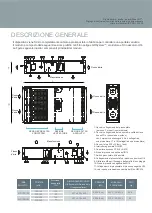
The figu
re below shows the main components of the module.
PREFILTER AND
GRSYSTEM SECTION
FAN
SECTION
ABSOLUTE FILTER
SECTION
1-
Pressure switch connection cable
(black with 2 terminal blocks joined together)
2-
Zonair3D
TM
air quality probe connection cable
(probe not included), with 4 marked terminals, 5 and 6
attached to strip, 17 and 18 (attached
to strip)
3-
230 V network cable (2 earth)
4-
Main ON/OFF switch
5-
PCB registration cover (4 M5 bolts)
6-
H14 positive pressure tap
7-
Differential pressure switch
8-
Connection to the H14 positive pressure switch
9-
M5 threads f
or fixing
the anchor brackets
10-
H14 negative pressure tap
11-
Connection to the H14 negative pressure switch
12-
Red LED to indicate HEPA1
4 filter
change
Maintenance
Maintenance
PRODUCT
RANGE
FLOW
(m
3
/h)
UNIT DIMENSIONS
H x W x L (mm)
CONSUMPTION
(KW)
VOLTAGE AND
FREQUENCY
WEIGHT
(kg)
Thank you for choosing Zonair3D
TM
products.
Please take a few minutes to read this manual carefully before
using your AIR PRO 100-300.
AIR PRO 100
180/150
207 x 639 x 929
0,028 (1 un)
230
V - 50/60
Hz
45,5
AIR PRO 300
270/200
0,056 (2 un)
230 V - 50/60
Hz
46
207 x 639 x 929
200/165
300/220
Pressure available
(Pa) *
100
50
100
50


