10
W-O/B: First stage heat. When energized (W1 made to R),
energizes first-stage heat or reversing valve for HP.
G:
Blower. When energized (G made to R),
energizes the indoor blower.
Y:
First stage cool. When energized (Y1 made to R),
energizes first stage cooling.
R:
HVAC unit 24V power. Powers the DIGI3U board
and zone thermostats.
C:
HVAC unit 24V power return.
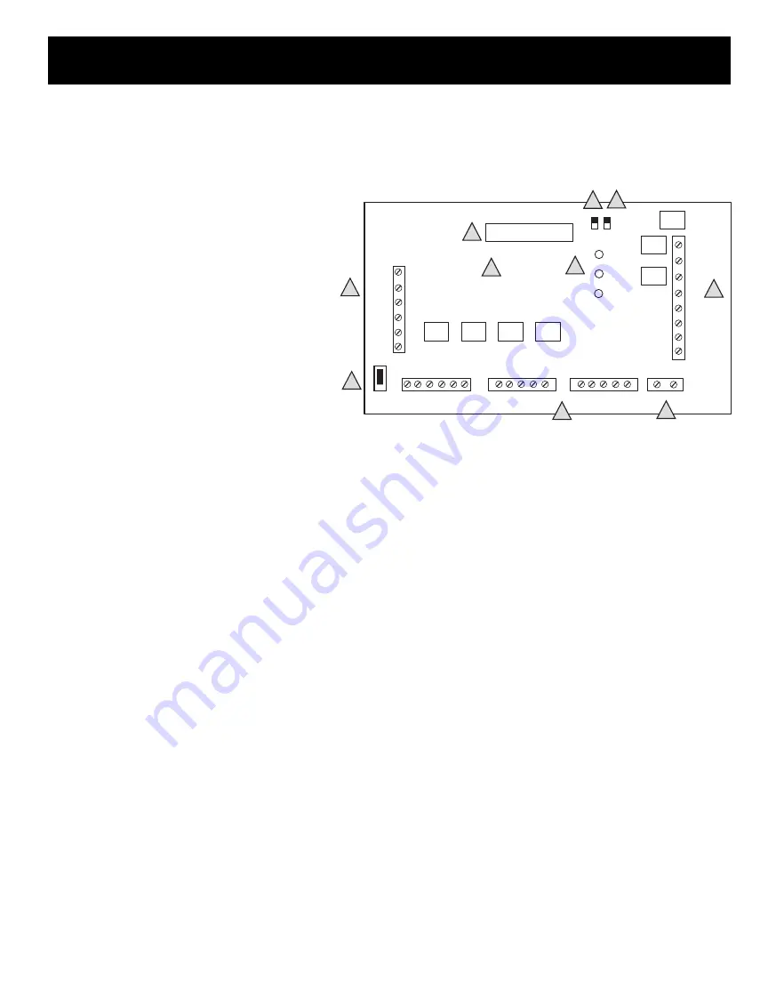
B. Thermostat Terminals
– Connects up to three zone ther-
mostats.
W:
Heat call. When energized, requests the DIGI3U
to run in heat mode.
W2: Used in HP STAT 1 only to energize emergency heat.
Not used in G/E.
R:
HVAC unit 24V power.
Y:
Compressor input.
G:
Blower Fan – When energized (G made to R), requests
the DIGI3U to turn on the indoor blower fan.
C:
HVAC unit 24V common.
C. Damper Terminals
– Connects dampers for up to three zones and
damper power supply.
TR1/TR2: 24V AC transformer terminals. This transformer powers
only the zone dampers and size properly.
1 1: Zone damper 1.
When energized, powers zone damper 1 closed.
2 2: Zone damper 2.
When energized, powers zone damper 2 closed.
3 3: Zone damper 3.
When energized, powers zone damper 3 closed.
D. Damper Status LEDs
– On when corresponding zone damper is
being powered closed.
E. Microcontroller
– Responsible for activation and control of the
unit based upon thermostat input. Occasionally software upgrades
may become available. If so, the DIGI3U software can be field
upgraded by changing this microcontroller.
F. HVAC System Status LEDs
– Indicates what the DIGI3U is
energizing on the HVAC system.
Y:
Compressor, yellow.
G:
Blower, green. On when the indoor blower is energized.
W-O/B: Heat or reversing valve, red. On when first stage heat or
reversing valve is energized.
W2:
Heat, red. Emergency heat is energized for heat pump operation.
PWR: Power, orange. On when power at R and C and the Power
Switch is on. Flashing when in Capacity Control cut out mode.
See Status Lights section for further information.
G. Power Switch
– When OFF, power from the HVAC unit transformer is
disconnected from the DIGI3U and thermostats. When ON, power from
the HVAC unit transformer is supplied to the DIGI3U and the zone
thermostats.
H. SS
– Terminals for capacity control.
I. JP1 O/B Jumper
– For heat pump application only. Place in O or B
position for proper reversing valve action.
J. JP2 HP/GE Jumper
– Place on proper pins for desired application.
SYSTEM CONTROLLER – UNIVERSAL GE/HP
1
1
2
2
3
3
TR1
TR2
o o o o
R Y O/B W2 G C
R Y W G C
R Y W G C
S
R
Y
G
W-O/B
W2
C
O O O
LED
Y
W-O/B
W2
G
DPR1
DPR2
DPR3
GE
HP
B
POWER
SWITCH
DIGI3U
STAT 2
STAT 3
STAT 1
O
PWR
CONTROL CHIP
O
O
LED
S
A
B
J
G
H
I
F
E
D
C
JP2
JP1
W
COMPONENTS
A. HVAC Unit/LAT Terminals
– Connects to HVAC unit.


