12
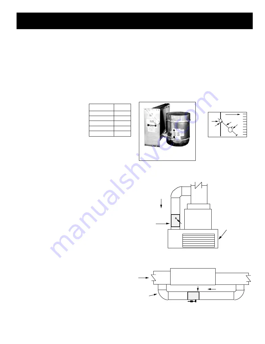
The barometric bypass damper is for systems 5 tons or under. It utilizes
a weighted damper blade to maintain constant duct pressure. This
allows for easy installation without the need for electrical power or
wiring. The round barometric damper can be installed in any position. It
is an efficient solution for small system fan capacity control.
SIZING:
When only the smallest zone is calling, the maximum
amount of excess supply air will flow through the bypass damper. To
determine the proper size bypass damper to use, do the following steps:
Step 1: Calculate bypass air volume as follows.
A) Calculate total air volume at 400 CFM
per ton.
B) Calculate air volume of smallest zone in
CFM.
C) Calculate bypass air volume by subtract-
ing the smallest zone air volume from
the total.
(A - B = C)
Step 2: Select damper from sizing table.
Once you have calculated the bypass air volume from Step 1, use the
BAROMETRIC BYPASS SELECTION TABLE. From the table, select the
bypass damper with the CFM rating equal to or greater than the value
calculated in Step 1. For rectangular barometric dampers, use a
ductulator to convert from round to rectangular.
If bypassing more than 2000 CFM, use electronic bypass damper.
Example:
You have a 4 ton system. Your smallest zone will use 500
CFM. The total CFM is 1600 CFM (400 * 4). Your bypass CFM is 1100
(1600 - 500). From the table, you determine that a 12” bypass damper
is needed.
Do not use the barometric bypass in any system over 5 tons.
For systems over 5 tons, or to bypass more than 2000 CFM, use the
electronic bypass.
RECTANGULAR & ROUND
BAROMETRIC BYPASS
BYPASS DAMPERS – BAROMETRIC
AIRFLOW
1
2
4
3
1. Damper Shaft
2. Lock Nut
3. Lever Arm
4. Counter Weight
BAROMETRIC BYPASS
DAMPER
Diameter
CFM
9”
650
10”
800
12”
1200
14”
1600
16”
2000
BAROMETRIC BYPASS
SELECTION TABLE
INSTALLATION
The round barometric bypass damper can be installed in any position.
This damper is factory set for horizontal installation and can be field
modified for vertical installation. Do not run speed screws into damper
housing. Screws may interfere with damper travel. Make sure counter
weight is not obstructed in any way.
a)
Install the bypass damper between the supply and return
plenums of the unit. It must be the first tap off the supply plenum.
b)
Be sure the air flows through the damper in the proper direction
as indicated by the arrow on the damper. Airflow is always
from supply to return plenum. Be certain the damper shaft
is horizontal.
c) Loosen counter weight with Allen wrench.
d)
Loosen lever arm from damper shaft and allow to hang straight
down.
e)
Fully close damper by grabbing damper shaft on side attached
to lever arm and turning clockwise until it stops.
f)
While holding the damper fully closed, rotate the lever arm a
little to the right (facing the damper) and then screw in to
tighten to the damper shaft. Then tighten lock nut.
g)
Be sure the damper is being held closed by the counter weight.
Proceed to setup
.
AIRFLOW
AIRFLOW
RETURN
BAROMETRIC
BYPASS
HORIZONTAL APPLICATION
SHEET METAL
PIPE
SUPPLY
PLENUM
A/C UNIT
OR
FURNACE
A/C UNIT
OR
FURNACE
RETURN
AIR
PLATFORM
BAROMETRIC
BYPASS
RETURN AIR GRILLE
AIRFLOW
SUPPLY
PLENUM
VERTICAL APPLICATION


