9
SYSTEM CONTROLLER - HEAT PUMP
120-130
25 41
33
40 50
45
115 125-145 5 25
15
TIME
HI
LO
BP
1
1
2
2
3
3
4
4
TR1
TR2
DPR 1
DPR 2
DPR 3
DPR 4
ON
OFF
LV
LV
Y2
G
W2
Y1
R
C
STAT 1
STAT 2
STAT 3
STAT 4
GE
W2
R Y G C
E R Y G C
}
LAT
OAS-
OAS+
Y1
G
W1/OB
Y2
HP
FF
O/B
W1
OB
R Y G C
R Y G C
R Y G C
R Y G C
R Y G C
R Y G C
ZONE 1
THERMOSTAT
ZONE 2
THERMOSTAT
ZONE 3
THERMOSTAT
ZONE 4
THERMOSTAT
Z
ONEX
DIGITRACT
MODEL: DT4U
W1
OB
W1
OB
W1
OB
W1
OB
OB
OB
OB
OB
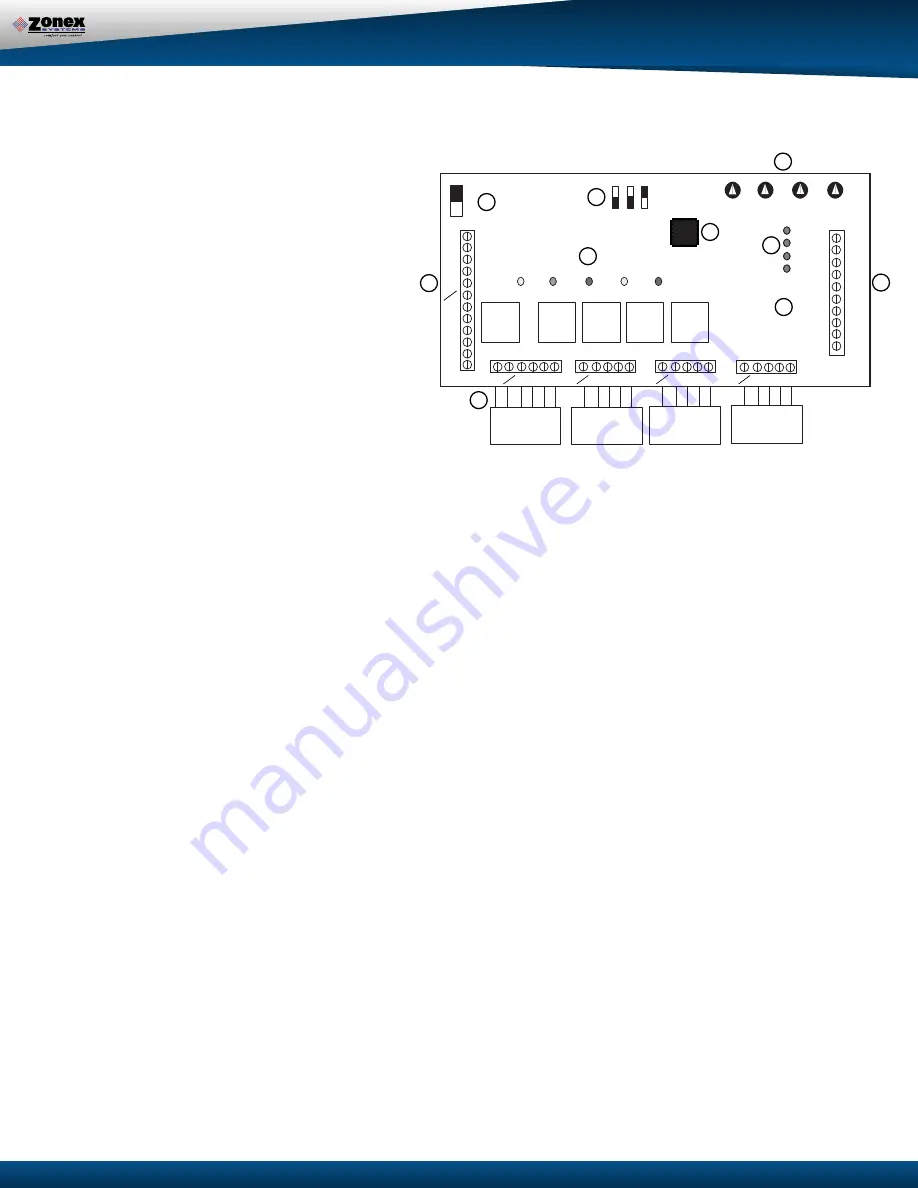
A. HVAC Unit/LAT Terminals
- Connects to HVAC unit
and Leaving Air Sensor (LAT).
LV LV: LAT terminals. The LAT monitors the leaving air
temperature.
OAS: Optional Outside Air Sensor for use in Fossil
Fuel / Dual Fuel applications.
O/B: Reversing Valve. When energized (O/B made to
R), engages the heat pump reversing valve.
W2: Auxiliary Heat. When energized (W2 made to R),
turns on the heat pump auxiliary heat.
G: Blower. When energized (G made to R), energi-
zed the indoor blower.
Y1: First stage cool. When energized (Y1 made to R),
energizes first stage cooling.
Y2: Second stage cool. When energized (Y2 made to
R), energizes second stage cooling.
R: HVAC unit 24 V power. Powers the Digitract 4
board and zone thermostats.
C: HVAC unit 24V power return.
B. Thermostat Terminals
- Connects up to four zone
thermostats.
E: Emergency Heat. On STAT 1 only. Connected to
E terminal on STAT 1.
O/B Reversing valve signal. “O” Energizes reversing
value in cool mode. “B” energizes reversing value
in the heat mode.
R: HVAC unit 24V power.
Y: Cool call. When energized (Y made to R),
requests the Digitract 4 to run in cool mode.
G: Blower Fan. When energized (G made to R),
requests the Digitract 4 to turn on the indoor
blower fan.
C: HVAC unit 24V common.
C. Damper Terminals
- Connects dampers for up to four
zones and damper power supply.
TR1/TR2: 24V ac transformer terminals. This transfor-
mer powers only the zone dampers.
1 1: Zone damper 1.
When energized, power zone damper 1 closed.
2 2: Zone damper 2.
When energized, power zone damper 2 closed.
3 3: Zone damper 3.
When energized, power zone damper 3 closed.
4 4: Zone damper 4.
When energized, power zone damper 4 closed.
D. Damper Status LEDs
- On when corresponding zone
damper is being powered closed.
E: Board Number
- This number indicates the circuit
board number and revision. You must know this
number if conferring with technical support.
F. Special Function Jumpers
GE/HP jumper
- Place on proper pins for desired application.
O/B jumper
- For heat pump application only. Place in O or B
position for proper reversing valve action.
FF fossil fuel jumper
-Place jumper in FF position to use fossil
fuel features.
G. Microcontroller
- Responsible for activation and control of the
unit based upon thermostat input.
H. HVAC System Status LEDs
- Indicates what the DT4U is energiz-
ing on the HVAC system.
Y1: Compressor, yellow On when the 1st-stage cool is energized.
Y2: Compressor, yellow On when the 2nd-stage cool is energized.
G: Blower, green. On when the indoor blower is energized.
O/B: Reversing valve, red. On when the reversing value is energized.
W2: Auxiliary heat, red. On when the auxiliary heat is energized.
PWR: Power, orange. On when power at R and C and the power
Switch is on. Flashing when in Capacity Control cut out mode.
See Status Lights section, page 9, for further information.
I. Power Switch
- When OFF, power from the HVAC unit transform-
er is disconnected from the Digitract 4 and thermostats. When
ON, power from the HVAC unit transformer is supplied to the
Digitract 4 and the zone thermostats.
J. Adjustable Potentiometers
- For HIGH limit, LO limit, TIME change-
over and BALANCE POINT (BP). Use these potentiometers to adjust
limits for a customized job. From factory the settings are 145° high,
45° low, 15-minute changeover and 33° balance point.
A
I
F
H
J
D
C
B
G
E
COMPONENTS
E


