8
Heat Pump operation “O” reversing valve
Cool Call – When a majority active cool call is received by the GEN II controller, Y1, O/B and G
LEDs are illuminated; and the outputs are energized (within 1.5 to 3 minutes). After 3 minutes, if
the leaving air temperature is 58°F (14°C) or above, Y2 will energize for 2-stage systems.
Y2 will
de-energize when it drops below 50°F and re-energize when it rises above 58°F.
If the supply air
temperature drops one degree below the Cool cut-out temperature, Y1 and Y2 will de-energize
“B” reversing valve – Sequence of operation is the same: O/B is energized in the heat mode.
Heat Call - When a majority active heat call is received by the GEN II controller, Y1 and G LEDs are
illuminated; and the outputs are energized (within 1.5 to 3 minutes). If after 3 minutes the leaving
air temperature is 94°F (34°C) or less, Y2 will energize. If after 6 minutes of run time the leaving air
temperature is 91°F (32°C) or less, W2 will energize. If the supply air temperature exceeds 126°F
(52°C), Y1, Y2 and W2 (if energized) will drop out; and Y1 can then energize after a 5-minute time
delay. NOTE: If the system fan is configured for “AUTO” on the GEN II controller, the “G” output
will be de-energized in the temperature cut-out mode.
When the last active call satisfies, the GEN II controller goes into a 5-minute purge cycle with all
supply dampers closing; then all dampers modulate open for ventilation.
GENERAL INSTALLATION INSTRUCTIONS
for 5 minutes.
Heat Pump operation “B” reversing valve
By placing the O/B jumper (B) on both pins, the GEN II controller is configured for “B” reversing
valve operation. The operation and setup procedures are the same as with “O” mode reversing
valve, except the reversing valve will be energized for heat operation.
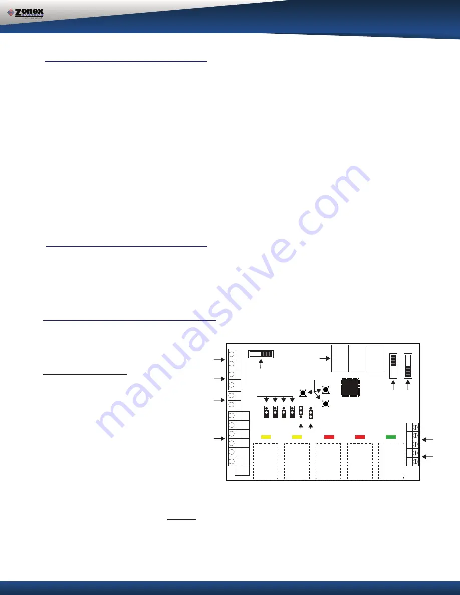
GEN II-R
Heat Pump Basic Configuration
The
GEN II-R
controller is shipped from the
factory for Gas Electric operation.
The controller must be field configured for
Heat Pump operation
.
Heat Pump configuration:
1. Switch controller to OFF
(E)
.
2. Set the O/B jumper
(F)
on one pin for “O”
reversing valve (energizes for cool)
or
Set the O/B jumper
(F)
on both pins for “B”
reversing valve (energizes for heat).
3. Set the HP jumper
(F)
on both pins for Heat
Pump operation.
4. Set the Priority jumper
(F)
on one pin.
5. Set the TIME / TEMP jumper
(I)
on the
middle and upper pins.
6. Set NIGHT / DAY switch
(J)
for DAY position.
7. Set LOCK / UNLOCK switch
(K)
to UNLOCK.
8. Switch the controller to ON
(E)
.
9. Press the UP button
(H)
, and verify the “H” (cut-out) temperature reads 126°F (52°C) on the
controller display
(G)
.
NOTE: The heat cut-out temperature
must not
be changed from the factory setting.
GEN II-R
7 2
SET
DN
UP
S
S
GND
B
ON
AUTO
TIME/TMP
TIME
EH
O/B
HP
PRI
NIGHT
DA
Y
UNLOCK LOCK
OFF ON
G
W2
W1
Y2
Y1
TC
TC
TR1
TR2
TR1
TR2
Y1
Y2
W1
W2
G
R
HP
GE
O/B
R
Y1
Y2
G
W2
A
A
B
C
D
E
F
G
H
I
J
K
L
M
OUT
IN


