background image

9

3. RAISE – Press the DN button.  After “C” is displayed, immediately release the DN button, and 

press the UP button.  Hold until the desired temperature reading is displayed; then release.

4. Press the DN button to verify the new cool cut-out temperature. 

Adjust 2

nd

Stage Cut-in Time Delay

1. To  increase  the  Y2  and  W2  cut-in  delay,  press  and  hold  the  SET  and  DN  buttons 

(H)

simultaneously.  When 03 appears in the display, release the buttons and immediately press 

the UP button and hold until the desired delay time is displayed, and release.   The time delay 

is fully adjustable from 3 - 20 minutes.  To verify the change, press and hold the SET and DN 

buttons simultaneously until the delay time is shown, and release. 

2. To  decrease  the  Y2  and  W2  cut-in  delay,  press  and  hold  the  SET  and  DN  buttons 

(H)

simultaneously.  When delay time appears in the display, release the buttons and immediately 

press the DN button and hold until the desired delay time is displayed, and release.  To verify 

the change, press and hold the SET and DN buttons until the delay time is shown, and release. 

Configure Y2 and W2 Cut-in for Time Delay and Thermostat Demand Only

1. Place the 2

nd

stage configuration jumper 

(I)

on the middle and lower pins -

TIME

.

2. If the Y2 cut-in time delay must be changed from the factory setting of 03 (3 min), follow the 

above procedures to raise or lower the time delay value.

NOTE:

The  cut-in  delay  timing  for  W2  (Aux  Heat)  is  set  for  approximately  3  minutes  in  the 

control program and cannot be manually changed.

3. Verify time delay value by pressing the SET and DN buttons simultaneously. 

HEAT PUMP ADVANCED FEATURE CONFIGURATION

GEN II

Heat Pump Advanced Feature Configuration 

Heat Pump Capacity Control - Cool and Heat cut-out temperature adjustment

When the 

GEN II

controller is configured for Heat Pump (HP jumper 

(F)

on both pins), the Cool and 

Heat cut-out temperatures are 45°- 126°F (7°- 52°C).  The cut-out temperatures can be changed 

with the following procedure:

Heat  cut-out  temp 

– To  eliminate  the  possibility  of  the  Heat  Pump  tripping  out  on  high  head 

pressure or short cycling in the heat mode, the heat cut-out temperature should never be changed 

from the factory setting of 126°F (52°C).

1. 

Cool  cut-out  temp

– Press  the  DN  button 

(H)

;  “C”  will  be displayed,  then  the  cut-out 

temperature.

2.   LOWER – Press the DN button.  After the “C” is displayed, continue to hold the DN button until 

the desired temperature is displayed; then release.

NOTE: The controller will not change the Cool cut-out lower than 40°F (4°C).

2nd Stage Heat and Cool Cut-in / Cut-out Configuration

The GEN II controller is set up at the factory to stage Y2 and W2 cut-in operation based on a 3-minute 

time delay and supply air temperature. This is done using the TIME/TEMP (I) jumper. Time may be 

field configured from 3-20 minutes by the contractor during system configuration. The cut-in tempera-

tures are fixed in the controller program at 58°F (14°C) and higher for Y2 and 120°F (48°C) and lower 

for W2. The GEN II controller second stage cut-out temperature is fixed in the controller program at 

50°F (10°C). Y2 will de-energize when it drops below 50°F and re-energize when it rises above 58°F. 

If the air temperature drops below the low cut-out (45°F) Y1 and Y2 are de-energized and the control-

ler will go into a 5 minute purge mode. After 5 minute purge, if the temperature has risen above the 

low cut-out Y1 is re-energized. Heat W1 and W2 will de-energize if leaving air temperature rises above 

heat cutout and will be locked out for 5 minutes. After 5 minute lockout, if a heat call remains and 

leaving air temperature is lower than heat cutout, W1 will re-energize. By placing jumper on bottom 

two pins, a time only strategy may be configured into the system. ( see below);

Summary of Contents for GEN II -VVT

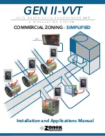
Page 1: ...58 GEN II VVT V O T E B A S E D A U T O C H A N G E O V E R V V T COMMERCIAL ZONING SIMPLIFIED GEN II System Controller A M O D U L A T I N G S Y S T E M Installation and Applications Manual...

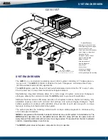
Page 2: ...on GEN II controller switch E Power light should light up and look at the display G on the GEN II controller and the 01 should appear on the display This indicates you are communicating with the first...

Page 3: ...on a call for heat place the EH jumper over both pins for several seconds and then remove Place the jumper tab on one pin 2 O B and HP jumpers F should both be on one pin or removed for GE operation...

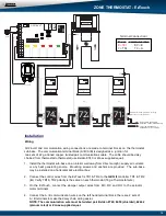
Page 4: ...g Zone Dampers 12 ZONE DAMPERS Bypass Dampers Slaving Bypass Dampers Bypass Installation IPC Static Pressure Controller 1 2 3 3 4 5 5 5 5 6 7 8 9 9 9 10 10 11 12 13 14 15 17 18 19 38 39 40 41 42 43 44...

Page 5: ...or with a simple startup diagnostic to minimize wiring errors and speed installation independent zo GEN II is recognized as the Industry s easiest commercial zone control system to install and wire Th...

Page 6: ...s the thermostats once per minute to determine the thermostat demand status for heat and cool The heat and cool changeover functions will operate by the type of changeover selected on the controller W...

Page 7: ...Operation for Electric Heat G Digital Display Leaving Air Temperature and configuration H Up Down Set Buttons High Limit Low Limit Set I Fan Jumper Continuous or Auto Staging Strategy Time Temperature...

Page 8: ...The GEN II controller is shipped from the factory configured for basic Gas Electric operation However the following should be checked as part of the initial installation setup procedures 1 EH jumper...

Page 9: ...n where the fan is controlled by the HVAC system fan control When a fan output is required from the GEN II controller on a call for heat place the EH jumper over both pins for several seconds and then...

Page 10: ...mp for Heat Pump Operation O B Jumper Heat Pump Only Reversing Valve Operation EH Jumper Set Up Fan Operation for Electric Heat G Digital Display Leaving Air Temperature and configuration H Up Down Se...

Page 11: ...2 will de energize B reversing valve Sequence of operation is the same O B is energized in the heat mode Heat Call When a majority active heat call is received by the GEN II controller Y1 and G LEDs a...

Page 12: ...on 4 Set the Priority jumper F on one pin 5 Set the TIME TEMP jumper I on the middle and upper pins 6 Set NIGHT DAY switch J for DAY position 7 Set LOCK UNLOCK switch K to UNLOCK 8 Switch the controll...

Page 13: ...controller is configured for Heat Pump HP jumper F on both pins the Cool and Heat cut out temperatures are 45 126 F 7 52 C The cut out temperatures can be changed with the following procedure Heat cut...

Page 14: ...ect the A B communication wires on the left hand terminal block there are 2 sets of A B terminals to make the daisy chain wiring easier NOTE The communication wire must be twisted pair Belden 8740 845...

Page 15: ...e and arrows and set the new ID ranging from 1 17 Tap to save changes to return to the home screen tap Select Damper Type The EzTouch needs to be configured for the type of damper that it is wired to...

Page 16: ...ostats are auto changeover but specific modes may be selected Heat Cool mode is the default System Heat Cool Tap on select Heat Cool Tap to save changes System Heat Only Tap on select Heat Only Tap to...

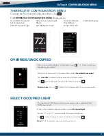
Page 17: ...Unoccupied Light Current Schedule Calibrate Display Set Temperature Mode Time Date Select Occupied Light Set Display Accuracy Temperature F C OVERRIDE UNOCCUPIED When a thermostat displays unoccupied...

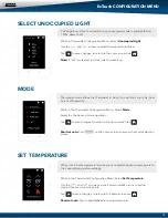
Page 18: ...to be set to heat cool cool only heat only of off operation EzTouch CONFIGURATION MENU While in the Thermostat Con guration Menu Select Mode Select the the desired mode operation Tap to save changes t...

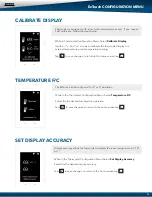
Page 19: ...the Thermostat Con guration Menu Select Set Display Accuracy Select the the desired display accuracy Tap to save changes to return to the home screen tap While in Thermostat Con guration Menu Select...

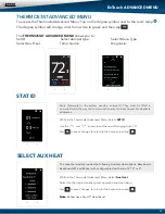
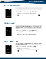
Page 20: ...emp The degree symbol will change color from white to green and then tap The THERMOSTAT ADVANCED MENU allows you to Set ID Select damper type Select Menu Type Select Aux Heat Temp Source Diagnostic ST...

Page 21: ...screen to return to the home screen tap EzTouch ADVANCED MENU set damper type round rectangular spring loaded vrf TEMP SOURCE Temp source allows the thermostat to display the outside air temperature...

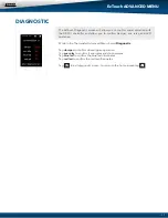
Page 22: ...and de energizes Tap blue led to con rm the blue led illuminates Tap red led to con rm the red led illuminates Tap to exit diagnostic screen to return to the home screen tap The EzTouch Diagnostic scr...

Page 23: ...l the heat call is satis ed Reheat when the zone temperature drops 2 below the heat set point the damper will modulate to approximately 40 providing air ow over the electric heat strips the AUX termin...

Page 24: ...board heater Wire from AUX C terminals to the 24v coil on a eld supplied SPDT relay Wire baseboard heat to the load side of the relay to the baseboard heater Wire from the AUX C to the 24v coil on a e...

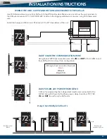
Page 25: ...TRANSFORMER TO POWER THE BYPASS DAMPER SUPPLY AIR LAT DISCHARGE SENSOR LAT SUPPLY LAT LOCATED BEFORE THE BYPASS ZONE DAMPER ACTUATOR DM SUPPLIED WITH ZONE DAMPER INTEGRATED STATIC PRESSURE CONTROL IP...

Page 26: ...whatever the 2nd stage temperature is set for When the room temperature reaches set point Y1 and Y2 will de energize O or B energize for the reversing valve circuit depending on con guration The G ci...

Page 27: ...NICATION WIRE DAISY CHAIN 24V POWER FROM GEN II Use 18 6 thermostat wire wire from SATouch to the RTU split system Make sure to match up the unit terminals to the SATouch terminals R Y1 Y2 W1 O B W2 G...

Page 28: ...egree symbol will change from white to green and then tap Once in the Thermostat Advanced Menu Select SET ID Use the and arrows and set the new ID ranging from 1 20 Tap to save changes to return to th...

Page 29: ...ap to save changes System Off Tap on select Off Tap to save changes Override Operation When the thermostat displays the unoccupied icon a 2 hour temporary override may be initiated by tapping the Over...

Page 30: ...screen tap Shortcut note Tap on to place the thermostat into 2 hour override mode THERMOSTAT CONFIGURATION MENU To access the Thermostat Con guration Menu Tap The THERMOSTAT CONFIGURATION MENU allows...

Page 31: ...ect the the desired operation mode Tap to save changes to return to the home screen tap Shortcut note Tap on the home screen to access the mode selection screen The brightness of the thermostat during...

Page 32: ...or F or C operation While in the Thermostat Con guration Menu Select Temperature F C Select the the desired temperature operation Tap to go back to the menu to return to the home screen tap CALIBRATE...

Page 33: ...room temp The degree symbol will change color from white to green and then tap The THERMOSTAT ADVANCED MENU allows you to Set ID Select Fan Mode Set Emergancy Heat Temp Source Select Unit Type Set 2nd...

Page 34: ...rows to set the 2nd stage temp range from 2 8 Tap to save changes to return to the home screen tap Fan operation is con gured for either Fan ON or AUTO When system is con gured for ON operation the Fa...

Page 35: ...to the home screen tap The SATouch Diagnostic screen will allow you to con rm communication with the GEN II controller and allow you to con rm the relays operation LED operation and report the leavin...

Page 36: ...AAA BB BB W1 REHEAT AAA AAA BB BB W1 REHEAT AVG 1 AVG 2 The following wiring diagram is used when temperature averaging is desired on a job This wiring diagram is to average two areas of a building f...

Page 37: ...e GEN II TR1 terminal All TR2 wires must be connected to the GEN II TR2 terminal Confirm the daisy chain wiring is correct at this time 3 Check A B wires for proper color code and connections polarity...

Page 38: ...call must now satisfy before the GEN II controller will recognize any of the initially calling thermostats The opposing call timer is factory adjusted for 10 minutes However the delay time can be fiel...

Page 39: ...ere made Thermostat security Set Point LOCK The GEN II system provides the ability to electronically lock all of the zone thermostats global When the thermostats are in the LOCK mode there will be a p...

Page 40: ...y feature minimizes visits to the thermostats To establish these default set points 1 EH jumper F place the jumper over both pins 2 Press the SET and DN button H simultaneously to engage default set p...

Page 41: ...backing plate to the wall with 3 screws provided 4 The GCLK is powered from TR1 and TR2 on the GEN II controller to terminals 1 and 2 on the time clock terminal base See wiring diagram below 5 The Nor...

Page 42: ...n to full close is 90 seconds ROUND MEDIUM PRESSURE DAMPER PART NUMBERS AND SIZES TYPICAL ROUND CAPACITIES These air quantities were derived from a duct sizing chart 0 1 friction loss per 100 of duct...

Page 43: ...life Two set screws connect the motor to the damper shaft allowing quick motor replacement if necessary Motor drive time from full open to full close is 90 seconds W HEAVY DUTY RECTANGULAR DIMENSIONAL...

Page 44: ...0000 10700 11900 13000 13800 14900 15200 16500 17500 30 1500 2100 2700 3425 4200 4950 5700 6350 7150 8400 9150 10000 11000 11800 12400 13800 14200 15000 16000 17400 18500 32 1600 2175 2850 3625 4425 5...

Page 45: ...op on it 5 Remember to allow a 16 gap in the duct for heavy duty rectangular dampers 6 Medium pressure rectangular dampers slide into a 3 wide cutout in the side of the preexisting ductwork 7 Minimum...

Page 46: ...r ROUND BYPASS DAMPER SELECTION The Zonex Systems STBP damper is used for round bypass applications When you know the bypass CFM requirements use the ROUND BYPASS SELECTION TABLE to confirm the round...

Page 47: ...4000 4500 5000 5500 6000 14 1167 1458 1750 2042 2333 2625 2917 3208 3500 4083 4667 5250 5833 6417 7000 16 1333 1667 2000 2333 2667 3000 3333 3667 4000 4667 5333 6000 6667 7333 8000 18 1500 1875 2250...

Page 48: ...e powered by a dedicated 24vac 40VA transformer 5 Follow the steps on the next page for Integrated Pressure Controller installation and set up BYPASS INSTALLATION 43 AIRFLOW AIRFLOW RETURN BYPASS HORI...

Page 49: ...bypass damper Drill hole into the side of the supply duct 2 after the bypass and before the 1st supply take off Mount pressure supporting block over hole align hole in block with hole in duct Use prov...

Page 50: ...ne dampers are closed except for calling zone Verify noise at zone registers is not excessive Adjust the Integrated Pressure Control LEFT to lower noise air ow or RIGHT to increase air ow until to noi...

Page 51: ...Web Site http www zonexproducts com Part GENIIMAN PATENTED PRODUCT Zonex Systems reserves the right to discontinue or change at any time specifications or designs without notice and without incurring...

Reviews: