10
Installation
Wiring
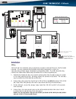
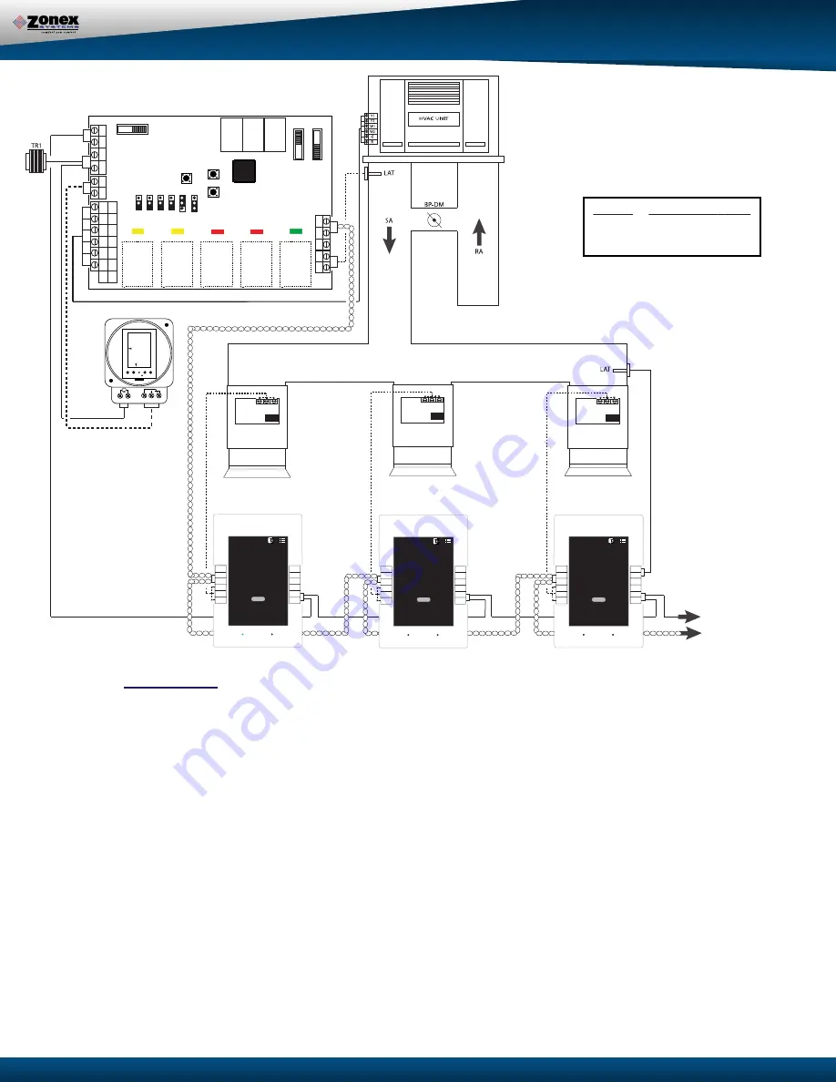
All 24-volt and communication wiring connections are made to terminal blocks on the thermostat
sub-base. The communication terminal block (A/B / A/B) is designed as a junction for
22 ga tinned copper, twisted pair communications cable. The cable should be daisy
thermostat to thermostat (use Belden 8740 or Zonex supplied equal).
1. Install the thermostat sub-base on an interior wall away from direct sunlight, supply air currents,
or any heat generating source. Mounting screws and anchors are provided. The sub-base
may be installed on a horizontal 2x4 electrical box.
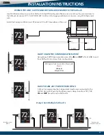
2. Connect the control wires from the EzTouch’s TR1 & TR2, to the
GEN II
controller TR1 & TR2
(
A
). Verify TR1 & TR2 polarity is the same on each thermostat (18 ga Thermostat wire)
.
3. On the EzTouch, connect the damper output wires from MC, RC and RO to the actuator
motor terminals.
4. Connect the A / B communication wires on the left hand terminal block; there are 2 sets of
A / B terminals to make the daisy chain wiring easier.
NOTE: The communication wire must be twisted pair Belden 8740, 8450 (shielded), 82442
(plenum rated) or Zonex supplied equal.
ZONE THERMOSTAT - EzTouch
Power Communication
R = TR1
RX = B
C = TR2 TX = A
Terminal Connections
DAISY CHAIN 24VAC AND
DATALINK CABLE (BELDEN 8740)
TO ALL ZONE EZTOUCH’S
EXPANDABLE TO 17 ZONES
chained from
two sets of
When the GEN II controller is powered up, the total number of addressed thermostats (EzTouchs) are
determined and verified on the display. This confirms the controller is communicating with all thermostats
in the system. If there are no active heat or cool calls detected, the supply dampers will modulate to 40%
open for ventilation mode. The system blower operation can be configured for constant ON or intermittent
Auto. The controllers are shipped from the factory for Auto fan.
The GEN II systems can be field configured for adjustable time based opposing call changeover, vote
based majority changeover, or priority vote changeover by thermostat assignment. The GEN II controller
is shipped from the factory for 10-minute opposing call changeover. The GEN II controller “polls” the
thermostats once per minute to determine the thermostat demand status for heat and cool. The heat and
cool changeover functions will operate by the type of changeover selected on the controller. When the
GEN II controller changes modes, a 5-minute purge cycle is initiated before the changeover is completed.
On active heat or cool calls, the non-calling zones will modulate to the closed position. When the last
calling zone is satisfied in either heat or cool mode, the GEN II controller terminates the HVAC outputs
after the next “poll” and the blower output will be de-energized (unless controller is configured for constant
fan) for a 5-minute purge cycle. During the purge cycle no heat or cool calls are recognized.
When the system is in the heating mode and calls for cooling are received, an opposing call timer strategy
operates. This timer is adjustable from 10 - 30 minutes. The factory default is 10 minutes. At the end of
the selected time period, if the opposing call is 3° away from set point, heating is turned off. After a 5-min-
ute purge mode, Cooling is turned on until the cool call is satisfied. If necessary, GEN II will return to the
heating mode, If all calls have been satisfied, dampers will modulate to the 40% open position for ventila-
tion. If the opposing zone strategy is not desired, this feature may be disabled.
This mode may be enhanced by adding Priority votes to each thermostat in the system, thereby weighting
certain zones more than others. This Priority mode allows you to select 0, 1, or 2 additional votes for a
thermostat that has unusual loads, like a conference room.
Minimum / Maximum damper positions can be set to provide ventilation. Each thermostat has Auxiliary
contacts that support and control a supplemental heat source i.e., baseboard, reheat, or hot water coil, to
meet the temperature requirements of any commercial application.
MODULATING DAMPER
DM-1
MODULATING DAMPER
DM-3
MODULATING DAMPER
DM-2
MC
RC
RO
MC
RC
RO
MC
RC
RO
7 2
SET
DN
UP
S
S
B
A
C1
GEN II-VVT
ON
AUTO
TIME/TMP
TIME
EH
O/B
HP
PRI
NIGHT
DA
Y
UNLOCK LOCK
OFF ON
G
W2
W1
Y2
Y1
TC
TC
TR1
TR2
TR2
TR1
Y1
Y2
W1
W2
G
R
HP
GE
O/B
R
Y1
Y2
G
W2
0 2 4 6 8 10 12
14
16
18
20
22
24
Mo
Tu
We
Th
Fr
Sa
Su
+1h
OVR AUTO
_
+
Mode
Menu OK
11:25
AM
1 2 3 4 5
M
GCLK
OUT
IN
MC
RO
RC
A
B
GND
AUX
DS
COM
DS
TR1
TR2
T-1
MC
RO
RC
A
B
GND
AUX
DS
COM
DS
TR1
TR2
T-2
MC
RO
RC
A
B
GND
T-3
AUX
DS
COM
DS
TR1
TR2
Optional Duct Temperature monitoring
(LAT sensor is not included)
24VAC
100VA

