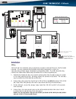
QUICK START AND COMMISSIONING
GEN II
QUICK START AND COMMISSIONING
The
GEN II
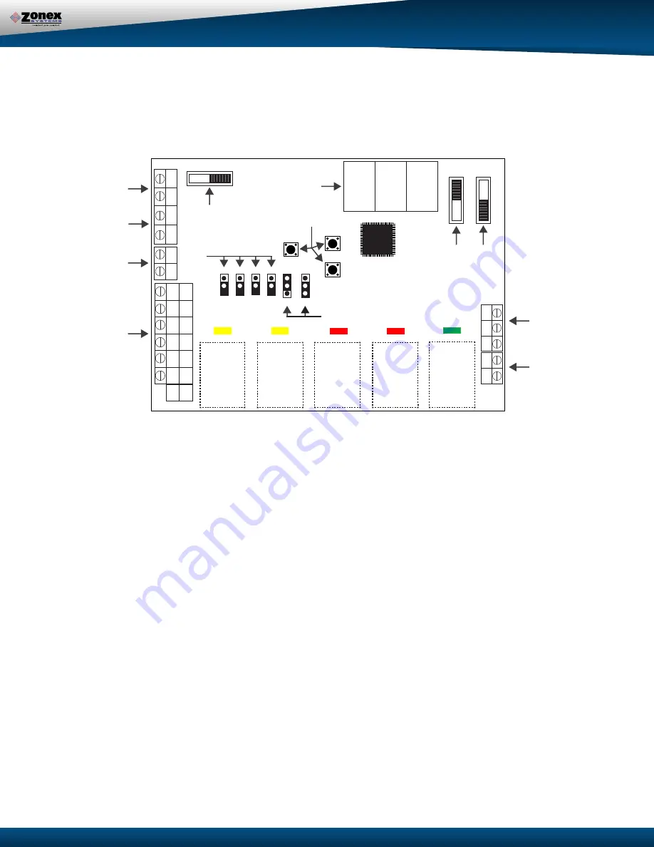
is equipped with a
Digital Display (G) that constantly displays Leaving Air Tem-
perature from the unit.
At startup, this display also reports the number of thermostats communicat-
ing with the
GEN II
controller. The display and 3 buttons (
H
) beneath the display provide the installing
contractor the ability to tailor the system to your specific application.
The
GEN II
controller is shipped from the factory configured for basic Gas/Electric operation.
However, the following should be checked as part of the initial installation setup procedures:
1.
EH
jumper
(F)
is installed by the factory on one pin for normal gas heat operation where the fan
is controlled by the HVAC system fan control. When a fan output is required from the GEN II
controller on a call for heat, place the
EH
jumper over both pins for several seconds and then
remove. Place the jumper tab on one pin.
2.
O/B
and
HP
jumpers
(F)
should both be on one pin or removed for GE operation.
3.
PRIORITY (PRI)
jumper
(F)
should be on one pin.
Note: If the Priority opposing zone strategy is to be used, this jumper position will be changed
after the initial system start-up is completed.
See Advanced Feature Configuration on page 21.
4. Set the Power Switch
(E)
to
ON
.
5. Set the
NIGHT DAY
switch
(J)
to the
DAY
position.
6. Set the fan jumper
(I)
to
AUTO
for intermittent operation or
ON
for constant ON operation in the
Occupied mode.
7. Place the
LOCK
–
UNLOCK
switch
(K)
in the UNLOCK position.
8. Place the
TIME/TEMP
jumper
(I)
on the middle and upper pins to control Y2 and W2 staging on
run time and supply air temperature.
GEN II-VVT
7 2
SET
DN
UP
S
S
B
ON
AUTO
TIME/TMP
TIME
EH
O/B
HP
PRI
NIGHT
DA
Y
UNLOCK LOCK
OFF ON
G
W2
W1
Y2
Y1
TC
TC
TR1
TR2
TR1
TR2
Y1
Y2
W1
W2
G
R
HP
GE
O/B
R
Y1
Y2
G
W2
A
A
B
C
D
E
F
G
H
I
J
K
L
M
OUT
IN

