26
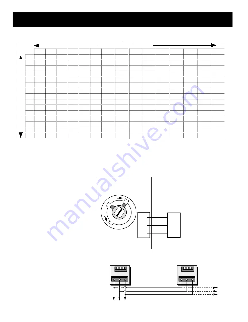
Bypass air in CFM. Calculated at 1500 FPM.
Formula used: B = W X H / 144 X 1500, where B = Bypass air in CFM, W = damper width in inches, H= damper height in inches, 144 = 144 sq.
inches per sq. ft., 1500 = 1500 FPM.
BYPASS POSITION INDICATOR
SLAVING BYPASS DAMPERS
Use only one Pressure Sensor when slaving two
or more Bypass Dampers together. Connect the
Pressure Sensor to one damper as described
above. Connect the slave dampers in parallel as
shown. Up to 4 dampers can be slaved to one
Sensor. The slaved dampers will self syn-
chronize each time the dampers reach full open
or full close.
24
28
32
36
40
44
48
8
2000
2333
2667
3000
3333
3667
4000
10
2500
2917
3333
3750
4167
4583
5000
12
3000
3500
4000
4500
5000
5500
6000
14
3500
4083
4667
5250
5833
6417
7000
16
4000
4667
5333
6000
6667
7333
8000
18
4500
5250
6000
6750
7500
8250
9000
20
5000
5833
6667
7500
8333
9167
10000
22
5500
6417
7333
8250
9167
10083
11000
24
6000
7000
8000
9000
10000
11000
12000
28
7000
8167
9333
10500
11667
12833
14000
32
8000
9333
10667
12000
13333
14667
16000
36
9000
10500
12000
13500
15000
16500
18000
40
10000
11667
13333
15000
16667
18333
20000
44
11000
12833
14667
16500
18333
20167
22000
48
12000
14000
16000
18000
20000
22000
24000
8
10
12
14
16
18
20
22
8
667
833
1000
1167
1333
1500
1667
1833
10
833
1042
1250
1458
1667
1875
2083
2292
12
1000
1250
1500
1750
2000
2250
2500
2750
14
1167
1458
1750
2042
2333
2625
2917
3208
16
1333
1667
2000
2333
2667
3000
3333
3667
18
1500
1875
2250
2625
3000
3375
3750
4125
20
1667
2083
2500
2917
3333
3750
4167
4583
22
1833
2292
2750
3208
3667
4125
4583
5042
24
2000
2500
3000
3500
4000
4500
5000
5500
28
2333
2917
3500
4083
4667
5250
5833
6417
32
2667
3333
4000
4667
5333
6000
6667
7333
36
3000
3750
4500
5250
6000
6750
7500
8250
40
3333
4167
5000
5833
6667
7500
8333
9167
44
3667
4583
5500
6417
7333
8250
9167
10083
48
4000
5000
6000
7000
8000
9000
10000
11000
WIDTH IN INCHES
HEIGHT IN INCHES
SLAVE
DAMPER
ACTUATOR
DAMPER
ACTUATOR
To Static Pressure Controller As Shown On The Bypass Wiring Diagram On The Next Page.
RC
RO
MC
TO NEXT SLAVE
BYPASS DAMPER
IF APPLICABLE
* *
RC RO MC
*
* *
RC RO MC
*
ROUND AND RECTANGULAR
BYPASS DAMPER MOTORS
CW
CCW
RC
MC
RO
SHAFT END MARKING IS PARALLEL
WITH DAMPER BLADE. DAMPER TRAVEL
IS 60
°
ON ROUND BYPASS AND 90
°
ON RECTANGULAR BYPASS
Note: Clockwise to close
on rectangular bypass and
counterclockwise on
round bypass.
BYPASS DAMPERS – ELECTRONIC
N/C
COM
N/O
101ASPC
Static
Pressure Control
RECTANGULAR BYPASS SELECTION TABLE


