41
The following applies to the
101CAPGE,
CAPL-2,
CAPL-4 and
SYCAP Setpoints:
There are two cut-out setpoints, one for heat and one for cool. The
digital display normally displays the leaving air temperature of the
HVAC/heat pump unit. By pressing the UP and DN buttons, the setpoints
can be viewed and changed.
Cool Setpoint
– To read the cool cut-out setpoint, press the DN button
until “C” appears and then release. The number that follows is the cool
cut-out setpoint. After a couple of seconds the leaving air temperature will
be redisplayed. To change the setpoint, press the bottom or down button
until the “C” is displayed, then immediately after the setpoint is displayed
press and hold the UP/DN button till setpoint is at the desired value.
Heat Setpoint
– To read the heat cut-out setpoint, press the UP button
until “H” appears and then release. The number that follows is the heat
cut-out setpoint. After a couple of seconds the leaving air temperature
will be redisplayed. To change the setpoint, press the top or up button
until the “H” is displayed, then immediately after the setpoint is displayed
press and hold the UP/DN button till setpoint is at the desired value.
Auxiliary Heat Setpoint
– For the SYCAP only, to read the auxiliary
heat setpoint, press the UP and DN buttons simultaneously until “E”
appears and then release. The number that follows is the auxiliary heat
setpoint. After a couple of seconds the leaving air temperature will be
redisplayed. To change the setpoint, immediately after the setpoint is displayed
press and hold the UP/DN button till the setpoint is at the desired value.
CALIBRATION
The digital display normally displays the leaving air temperature of the
internal thermometer. This thermometer is factory calibrated. If calibration
is ever required, turn the Thermometer Calibrator clockwise to lower the
temperature. Turn counterclockwise to raise.
CAPACITY CONTROLLERS – SETPOINTS, CALIBRATION
FIVE WIRE LINK
Zonex Systems’s patented Five Wire Link is one of the most important ele-
ments of the System 1000/2000 zoning system. Extra care should be made
to ensure the wiring is done correctly. The color code must be strictly fol-
lowed. Ensure the stripped wire leads are not touching each other at the ter-
minal blocks. If putting two wires into one terminal block, use the same
gauge wire for both and ensure they are seated properly.
You must ensure the wire is sized properly to match the power needs of
the number of dampers installed. The more dampers used, the greater the
current draw and the greater the voltage loss on the Five Wire Link. If too
much voltage is lost on the Five Wire Link, there will not be enough
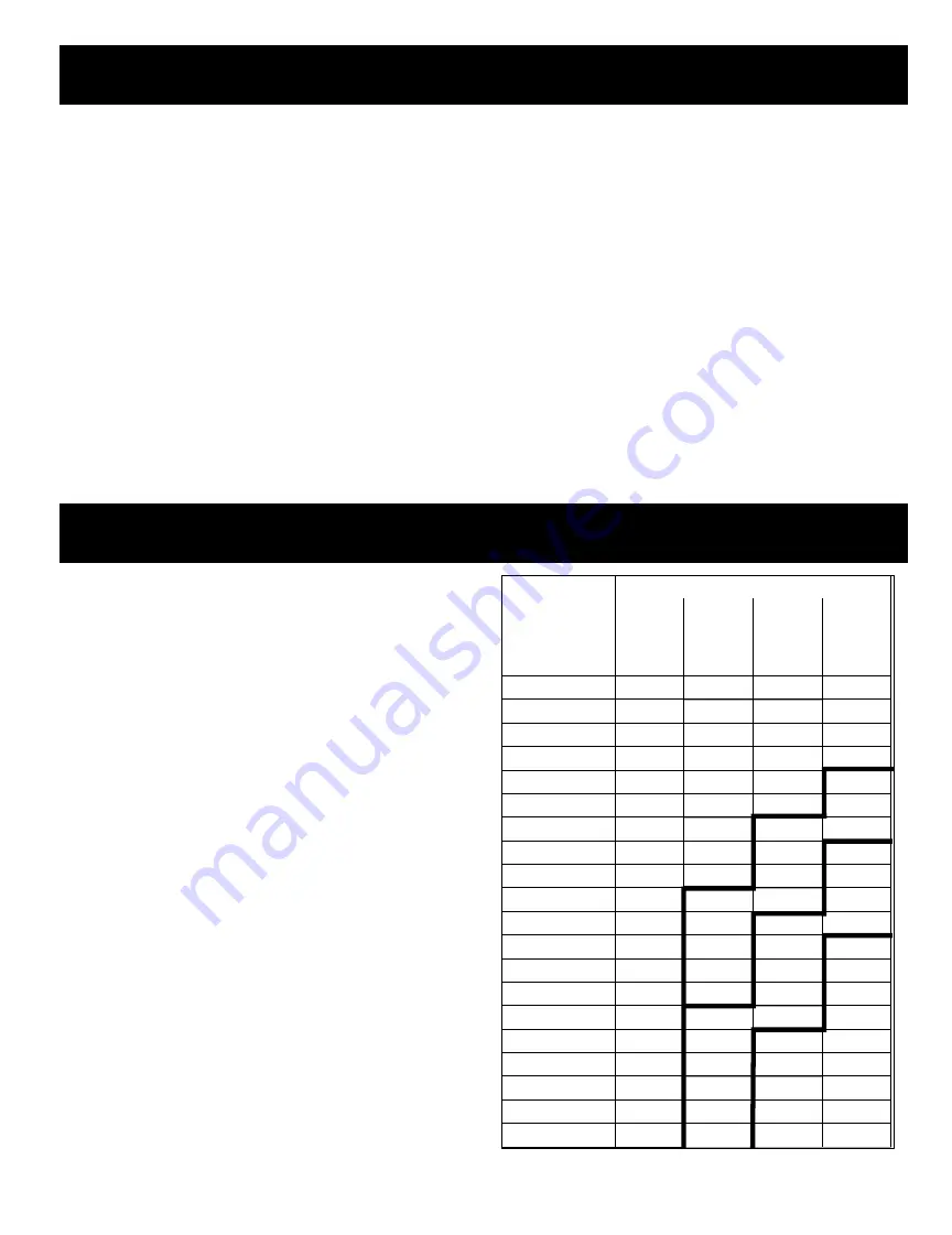
voltage at the zone dampers to properly operate them. To ensure the
correct wire size, use the following table. Select the row matching the
number of zone dampers you have. Move across horizontally to the
column that matches the distance from the System Controller to the
farthest damper. Use the wire size specified at the row/column
intersection.
To reduce wire size, you can run more than one Five Wire Link Daisy Chain.
Example: If you have 10 dampers, and the maximum distance is 200 feet,
you would need 12 GA wire. If instead, you used two Five Wire Links with
5 dampers on each, you would now only need 18 GA wire for each daisy
chain. Multiple daisy chains are wired color to color at the System
Controller.
NOTE: Never use less than 18 GA wire on the 5 Wire Link.
WIRE LENGTH
NUMBER OF
ZONE
DAMPERS
50'
100'
150'
200'
1
18 GA
18 GA
18 GA
18 GA
2
18 GA
18 GA
18 GA
18 GA
3
18 GA
18 GA
18 GA
18 GA
4
18 GA
18 GA
18 GA
18 GA
5
18 GA
18 GA
18 GA
18 GA
6
18 GA
18 GA
18 GA
16 GA
7
18 GA
18 GA
18 GA
16 GA
8
18 GA
18 GA
16 GA
16 GA
9
18 GA
18 GA
16 GA
14 GA
10
18 GA
18 GA
16 GA
14 GA
11
18 GA
16 GA
16 GA
14 GA
12
18 GA
16 GA
14 GA
14 GA
13
18 GA
16 GA
14 GA
12 GA
14
18 GA
16 GA
14 GA
12 GA
15
18 GA
16 GA
14 GA
12 GA
16
18 GA
14 GA
14 GA
12 GA
17
18 GA
14 GA
12 GA
12 GA
18
18 GA
14 GA
12 GA
12 GA
19
18 GA
14 GA
12 GA
12 GA
20
18 GA
14 GA
12 GA
12 GA


