background image


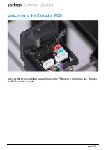
Unscrewing the Extruder PCB

Unscrew the two screws that secure the extruder PCB using a 2mm Allen key. Remove
the PCB from the extruder.

                            page 11 / 23

Summary of Contents for M200

Page 1: ...Heater and Thermocouple Replacement SOURCE https support zortrax com thermocoupler and heater replacement page 1 23 ...

Page 2: ... Unscrewing the Extruder PCB Extruder Lower Printed Cover Removal Heater and Thermocouple Removal from the Extruder New Heater and Thermocouple Assembly in the Extruder Extruder Lower Printed Cover Assembly Extruder PCB Assembly Plugging all Cables into the Extruder PCB Heater and the Thermocouple Assembly in the Hotend Hotend Assembly Plugging the Extruder Cable Material Guide Installation Pluggi...

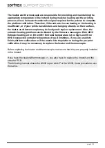
Page 3: ...he extruder heating problems are indicated by the firmware messages Error 010 Extruder heating error Error 011 Extruder temperature is too high and Error 013 Unexpected extruder temperature drop Sometimes if you are unable to finish platform calibration or if the nozzle hits the platform during the pre print calibration it may be necessary to replace the heater and thermocouple Before replacing th...

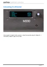
Page 4: ...Unloading the Material If the material is loaded into the extruder unload the material using the Material Unload the material option in the menu page 4 23 ...

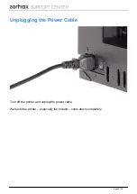
Page 5: ...Unplugging the Power Cable Turn off the printer and unplug the power cable Wait until the printer especially the hotend cools down completely page 5 23 ...

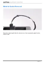
Page 6: ...Material Guide Removal Detach the material guide from the extruder cover Next separate the guide from the extruder cable page 6 23 ...

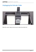
Page 7: ...Unplugging the Extruder Cable Detach the extruder upper printed cover and unplug the extruder cable page 7 23 ...

Page 8: ...Hotend Removal With a 1 5mm Allen key loosen the two screws that secure the hotend and remove the hotend from the extruder page 8 23 ...

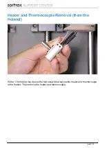
Page 9: ...Heater and Thermocouple Removal from the Hotend With a 1 5mm Allen key loosen the two screws that secure the heater and thermocouple in the hotend Then remove the heater and thermocouple page 9 23 ...

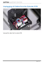
Page 10: ...Unplugging all Cables from the Extruder PCB Unplug all the cables from the extruder PCB page 10 23 ...

Page 11: ...Unscrewing the Extruder PCB Unscrew the two screws that secure the extruder PCB using a 2mm Allen key Remove the PCB from the extruder page 11 23 ...

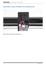
Page 12: ...Extruder Lower Printed Cover Removal Remove the extruder lower printed cover page 12 23 ...

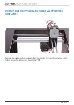
Page 13: ...Heater and Thermocouple Removal from the Extruder Remove the heater and thermocouple from the extruder block and from the heat shrink tubing Unplug the cables from the extruder PCB page 13 23 ...

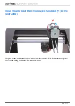
Page 14: ...New Heater and Thermocouple Assembly in the Extruder Plug the heater and thermocouple cables into the extruder PCB Put them through the heat shrink tubing and inside the extruder s block page 14 23 ...

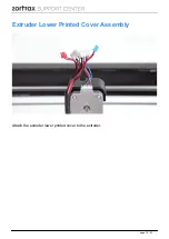
Page 15: ...Extruder Lower Printed Cover Assembly Attach the extruder lower printed cover to the extruder page 15 23 ...

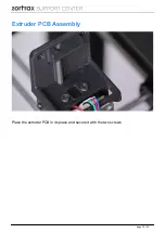
Page 16: ...Extruder PCB Assembly Place the extruder PCB in its place and secure it with the two screws page 16 23 ...

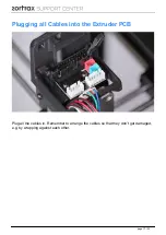
Page 17: ...Plugging all Cables into the Extruder PCB Plug all the cables in Remember to arrange the cables so that they don t get damaged e g by wrapping against each other page 17 23 ...

Page 18: ...heater and thermocouple into the hotend and firmly tighten the two screws that secure them using a 1 5mm Allen key Make sure that the screws don t go through the insulation that covers the wires this can happen if the heater goes too deep into the slot page 18 23 ...

Page 19: ...This picture shows the heater inserted correctly This picture shows the heater pushed too far into the slot in the hotend page 19 23 ...

Page 20: ...Hotend Assembly Insert the hotend into the extruder and tighten the two screws that secure it using a 1 5mm Allen key page 20 23 ...

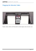
Page 21: ...Plugging the Extruder Cable Plug the extruder cable in and then attach the extruder upper cover to the lower cover page 21 23 ...

Page 22: ...Material Guide Installation Attach the material guide to the extruder cover Next secure the guide to the extruder cable with the material guide clamps page 22 23 ...

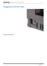
Page 23: ...Plugging the Power Cable Plug the power cable in Powered by TCPDF www tcpdf org page 23 23 ...

Reviews: