User Manual
This document is not allowed to
transmit without ZTE Corporation
’s
permission
©ZTE CORPORATION All rights reserved
24
4.2.2
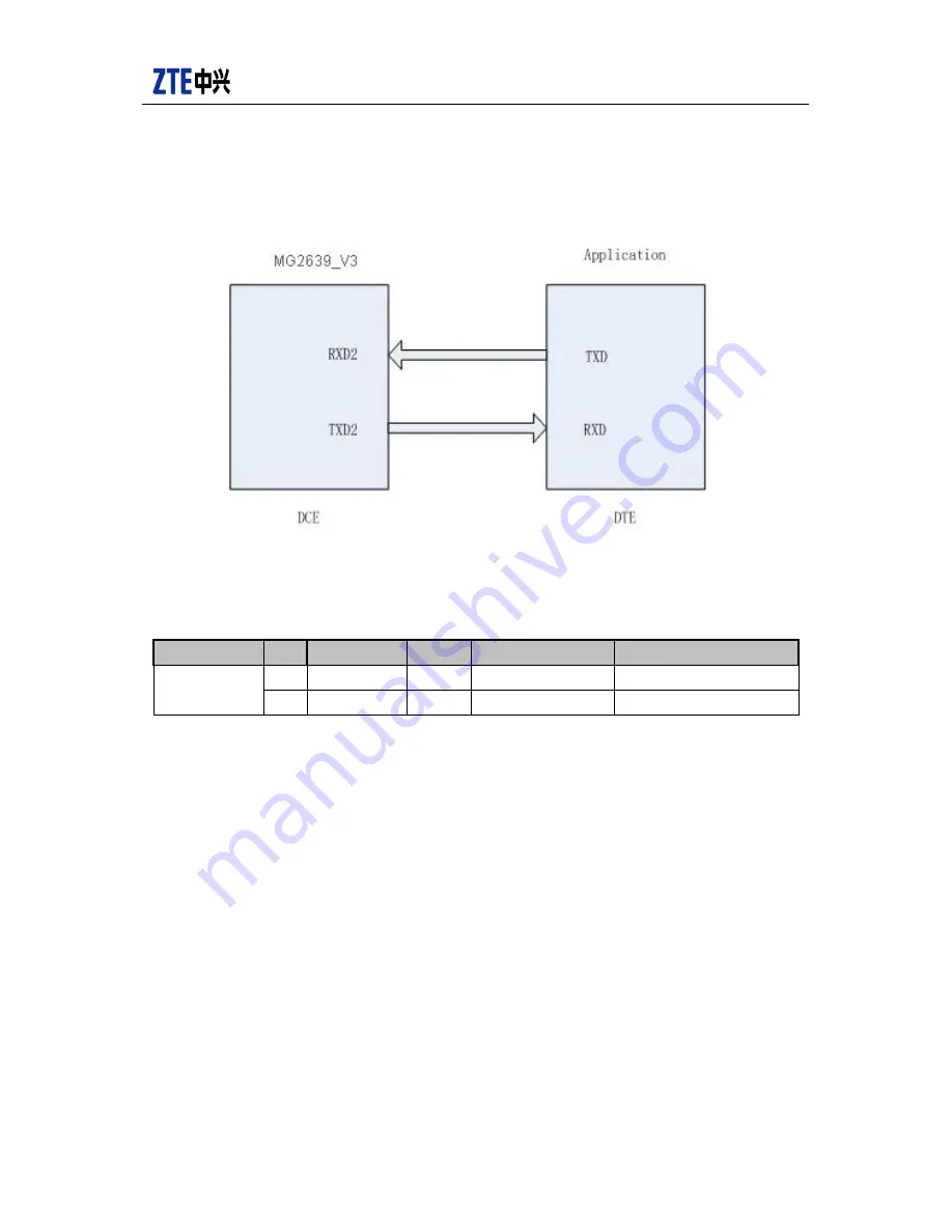
Descriptions of UART2 interface
Figure 4-6 UART2 DCE
-
DTE connection relationship diagram
See the definitions of UART2 interface in table 4-4.
Table 4-4 UART2 interface definitions
Classification
No.
Definitions
I/O
Descriptions
Remarks
UART
43
RXD2
Input
Receiving data
DTE transmits serial data
44
TXD2
Output
Transmitting data
DTE receives serial data
4.3
SIM card interf ace
MG2639_V3 module supports 1.8V or 3.0V SIM card. Refer to figure 4-7 for design.


