Chapter 2 System Structure and Components
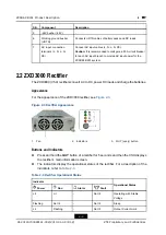
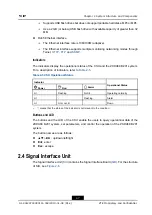
Indicator
Power
Run
Alarm
Fault
Operational Status
Lit
-
Flashing
-
Communication Failure
Lit
-
Lit
-
Alarm
Lit
Not lit
-
Lit
Fault
•
“-” means that the status of the indicator is not relevant to the condition.
Interfaces
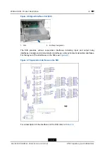
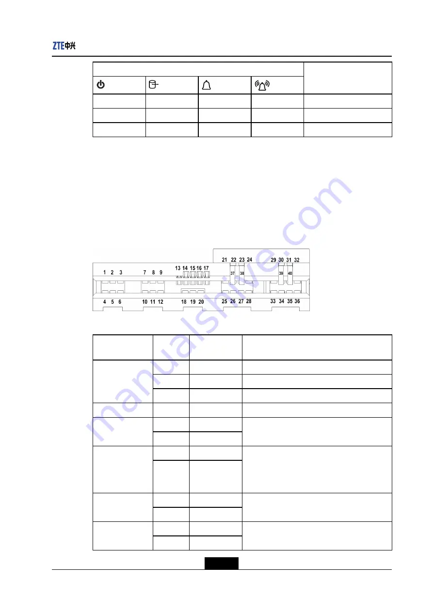
Input and output interfaces are laid at the back of the rectifier. For the interface layout of
the rectifier, see
. For a description of the pin definitions, refer to
The interfaces complete the electrical and signal connections between the rectifier and the
ZXDU68 B201 power system.
Figure 2-4 Rectifier Interfaces
Table 2-4 Pin Definitions of Rectifier Interfaces
Interface Name
Pin No.
Signal
Definition
Function
1 - 6
L
Connects the AC input phase cable.
7 - 12
N
Connects the AC input neutral cable.
AC input
interfaces
18 - 20
PE
Connects the protection ground.
-
13
-
Reserved
14
AA
Phase detection
interfaces
15
AB
Locates the phase where an operating rectifier is.
16
CAN-
communication
detection
interfaces
17
CAN+
A rectifier communicates with other devices
through the interfaces. For example, a rectifier
transmits data to the CSU, and the CSU issues
commands to a rectifier.
21 - 28
DC output
interfaces
29 - 36
OUTPUT-
Provide DC output power.
37, 38
Hot-plug pin (+)
Hot-plug pins
39, 40
Hot-plug pin (-)
Prevent sparks when a rectifier is installed into
the ZXDU68 B201 system.
2-5
SJ-20120703093141-002|2013-01-08 (R1.2)
ZTE Proprietary and Confidential


