Chapter 1 - System Architecture
Confidential and Proprietary Information of ZTE CORPORATION
7
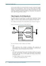
The TPU implements all functions of baseband data processing of all
full-duplex channels on a TDMA frame, and the conversion between
LapDm protocol and LapD protocol. It supports GPRS packet data
service functions, CS1, CS2, CS3, CS4 coding modes, MCS1, MCS2,
MCS3, MCS4, MCS5, MCS6, MCS7, MCS8 and MCS9 coding modes,
and 8PSK modulation modes.
ii. Radio Carrier Unit (RCU)
RCU modulates baseband signals to carrier signals and up-converts
frequency. At the same time, it down-converts the frequency of
received carrier signals. In addition, it can control the power
statically and dynamically in the downlink direction as required in
GSM specifications.
iii. Power Amplifier Unit (PAU)
PAU amplifies the power of the radio carrier to provide the BS
equipment with sufficient transmission power.
3. AEM
AEM implements the combination/distribution of air signals. It is
composed of three types of combiner/distribution units.
i. Combiner Distribution Unit (CDU)
CDU supports one 2-in-1 combiner unit and one 1-to-4 distribution
unit. It has two low noise amplifiers with extended receiving output
and one built-in duplexer.
ii. Receiver Distribution Unit (RDU)
RDU supports one 1-to-4 distribution unit and has two low-noise
amplifiers with extended receiving output and one receiving filter.
iii. Combiner Extension Unit (CEU)
CEU supports two 1-to-2 power distribution units and two 2-in-1
combiner units.
Through the combination of CDU, RDU and CEU, AEM provides
various site configurations for ZXG10-BTS (V2.9).
4. FCM
In the thermal design of the ZXG10-BTS (V2.9), one fan layer with two
fans is installed on each carrier shelf to ensure the system to work
normally since the carrier shelf is the major heat source.
FCM collects and monitors the temperature in the carrier shelf and use
the fans to dissipate the heat out of the cabinet.
5. PDM
PDM distributes the DC power supply (-48 V) to the modules, and
provides overload open-circuit protection and filtering of the basic
power input.
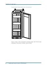
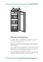
Figure 4 shows the positions of modules in a fully configured 40 W
single cabinet.
Summary of Contents for ZXG10-BTS
Page 4: ...This page is intentionally blank ...
Page 8: ...Figures 121 Tables 123 ...
Page 9: ...This page is intentionally blank ...
Page 10: ......


