Chapter 23 IPv6 VRRP Configuration
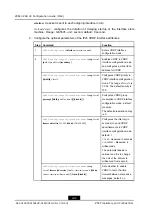
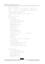
No authentication data
Check ttl enable
Vrrp accept mode enable
Out-interface send-mode is all
Tracked interface items: 0
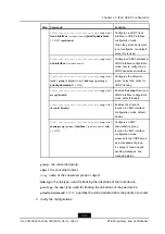
Interface
State
Policy
Reduce-Priority
Tracked detect items: 0
Admin-group is None
Vrrp run info:
State is Backup
6 state changes, last state change 17:05:34 1 day(s)
Current priority is 100
Master router is remote
Master router address is FE80:0:0:0:0:0:1:2
Master router priority is 255
Master Advertisement interval is 1.000 (s)
Master Down interval is 3.609 (s), no learn
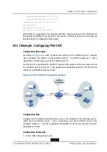
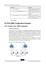
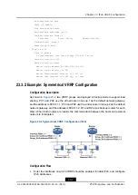
23.3.2 Example: Symmetrical VRRP Configuration
Configuration Description
As shown in
, two VRRP groups are deployed in backup mode to support load
sharing. PC1 and PC2 use the virtual router in Group 1 as the default network gateway,
and the address is FE80::1:1. PC3 and PC4 use the virtual router in Group 2 as the default
network gateway, and the address is FE80::1:2. R1 and R2 act as backup routers for each
other. When both routers are invalid, the communication between the hosts and external
network is interrupted.
Figure 23-2 Symmetrical VRRP Configuration (IPv6)
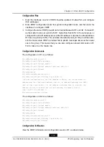
Configuration Flow
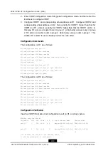
1.
Enter the interfaces on which VRRP should be enabled. Enable IPv6, and configure
IPv6 addresses.
23-7
SJ-20140504150128-018|2014-05-10 (R1.0)
ZTE Proprietary and Confidential

